Nikola Tesla Articles
Electricity at the World's Fair - Sept. 9, 1893
Aside from several distinguished members of the congress who remained to see the exposition, two notable figures attracted attention in the electricity building last week — Thomas A. Edison and Nikola Tesla. Mr. Edison paid several visits to the building, strictly in the capacity of a spectator, and greatly enjoyed his inspection of the exhibits. Mr. Tesla gave a number of experiments before invited guests and the general public. On Tuesday afternoon he repeated, at the agricultural assembly hall, the substance of his lecture on "Mechanical and Electrical Oscillators," which was delivered before the members of the congress on the preceding Friday. On this occasion he had for an audience von Helmholtz and a number of other scientists who had been unable to attend the first lecture. On Tuesday evening Mr. Tesla repeated his beautiful and interesting high tension and high frequency experiments in the dark pavilion of the Westinghouse company in electricity building before a number of foreign engineers, including W. H. Preece, H. D. Wilkinson, MM. Mascart and de la Touanne, Dr. Lobach, F. W. Tischendoerfer and others. He also instructed and entertained other parties of visitors at intervals during the week at the same place by similar demonstrations. In conversation with a representative of the Western Electrician, however, Mr. Tesla said that he considered his researches into oscillatory phenomena, and the results that he had already obtained in that direction, his greatest work, and that he hoped to continue his investigations until he could present the world a system of mechanical and electrical vibration of commercial utility.
The German historical exhibit of electrical apparatus which is illustrated on this page can be found in the central portion of the eastern gallery of the electricity building, and the collection, which has only lately been opened to the public, will well repay a visit, as it is alike instructive to the student and interesting to the casual visitor. Here are shown devices which are claimed to substantiate the assertion that three of the great applications of electricity — the electric-telegraph, the electric speaking telephone and long-distance power transmission — were first made in Germany. The articles shown were contributed largely by Siemens & Halske, of Berlin, although a number were obtained from the Imperial German Postoffice Department and other sources. The central feature of the display, at the back of the exhibit, is a bust of Werner von Siemens, the great German electrician, of heroic size, conspicuously placed under a large canopy. To the right, on a pedestal, is a life-sized bust of Sömmerring, for whom is claimed the honor of inventing the electric telegraph. On the left is a bust of Philip Reis, who is undoubtedly entitled to the distinction of having invented the first electric speaking telephone, crude though it undoubtedly was, the date being 1861. On either side of these busts are bas-relief heads of Gauss and Weber, all of the sculptured figures being outlined against a background of dark crimson cloth, which conceals the side of the building. On this background is also arranged a series of framed photographs showing the primary and secondary stations of the three-phase installation used in the Lauffen-Frankfort power transmission experiment, with pictures of the line construction and of the work accomplished by this electrically transmitted power at the Frankfort electrical exposition. One of the oil insulators used is also shown. It will be remembered that the Germans succeeded in transmitting 300 horse power over 100 miles at a pressure of 30,000 volts, and of this achievement they are naturally not a little proud. Arranged in front of the busts are a number of interesting relics. An effort was made to secure the apparatus used by Sömmerring in his first experiments with the galvanic telegraph, some eighty years ago, but without success, as the decedents of the noted physicist, who reside in Frankfort, would not consent to the removal of the instruments to America, even temporarily. Models of the Reis telephone instruments are shown, however. One of the most interesting features of the collection is the electro-magnetic telegraphic apparatus of Gauss and Weber, which was devised about 1833. It is big and clumsy, and the signals were recorded by means of a reading telescope and a mirror. A piece of the wire used in the first telegraph line in Goettingen in the year mentioned is shown, with printed copies of some interesting letters written at that time to the mayor of the town by Prof. Weber. Appropriately placed near the central bust is the first machine built in Germany on the dynamo electric principle. It was invented by Werner von Siemens, and brought out in 1866. This interesting exhibit has but one armature winding. It is carefully preserved. Among the other Siemens & Halske appliances is the first dynamo with a von Hefner-Alteneck drum armature, which dates from 1872, and a Gramme ring machine produced between '75 and '80. The latter was a commercial machine, with commutator and brushes that do not differ greatly from the type of to-day. Another machine that excites attention is an old flat ring dynamo, with an armature that also serves as a commutator by placing the brushes on the outside winding, as is done in the large Siemens & Halske generator in machinery hall. The Siemens & Halske display also includes the oldest unipolar dynamo, an old electric drill, an interesting collection of historical lamps, including the first differential arc lamp of von Hefner-Alteneck and the standard amyl-acetate lamp, and many measuring instruments, among which is a selenium photometer made by Werner von Siemens in 1877. The first electric locomotive built by Siemens & Halske, which was produced in 1879, is accorded a prominent position in the middle of the space, and it appears curious and antiquated when compared with the electric railway motors of the present day. In the northern portion of the space are many old instruments that are worthy of inspection. These include a number of the telegraphic appliances used by Siemens in the '40's, the original machine for pressing gutta percha for insulation, old resistance boxes, galvanometers and the like.
A number of the gallery exhibitors in the electricity building have united in issuing a neat souvenir for presentation to visitors. This memento consists of a booklet containing a portrait of Chief Barrett and views of the exhibits of the Ansonia Electric company, W. R. Brixey, Bates Manufacturing company, Commercial Cable company, North American Phonograph company, Edison Manufacturing company, Caldwell electric cloth cutter, Electrical Engraving company, Electric Appliance company, Electric Heat Alarm company, Eureka Tempered Copper company, Chas. F. Hall, Gamewell Fire Alarm & Telegraph company, McNeil-Tinder Electric company, Newman Clock & Manufacturing company, Reliance Gauge company, Weston Electrical Instrument company and others. The idea of this souvenir originated with George B. Clark, who displayed much energy in pushing the plan to completion.
Luther Stieringer, the designer of the electric fountains at the World's Fair, left for New York on Saturday. The evidence of Mr. Stieringer's second visit to the fair since the opening can be seen in the greatly improved operation of the fountains, which are now taking their rightful position among the great popular attractions on the grounds. Mr. Stieringer hopes to return before the close of the fair to inspect the exposition as a spectator.
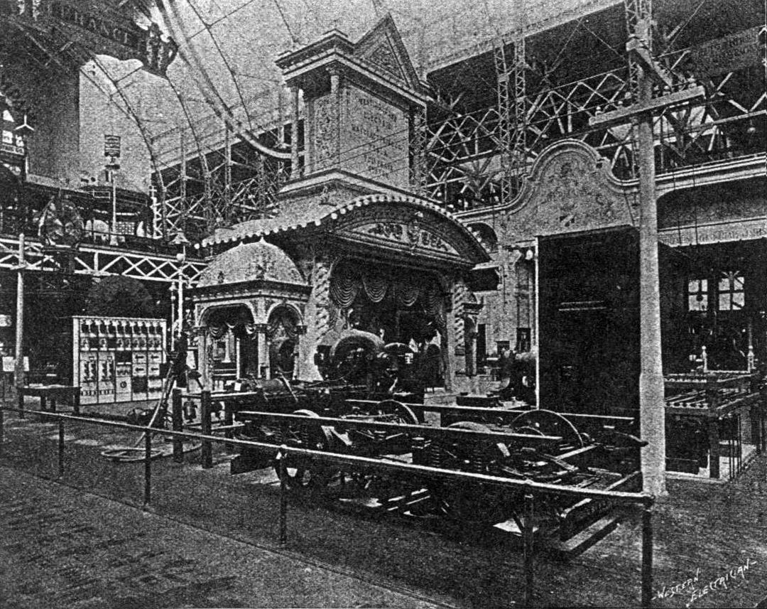
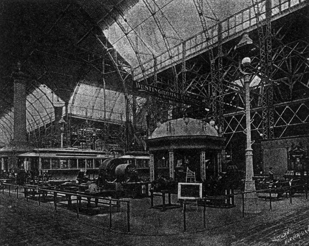
Of the four exhibit spaces in electricity building occupied by the Westinghouse Electric & Manufacturing company, the two most prominent, which are located in the nave of the building, are shown in Figs 2 and 3. This company has about 15,000 square feet of space in this building in addition to its great alternating incandescent plant in machinery hall. In the exhibit particular attention is paid to the transmission of power by the Tesla polyphase system. The space illustrated in Fig. 2 is that in the northern portion of the building. It contains the beautiful Westinghouse golden pavilion and also the Tesla generating station, although the machinery of the latter is not shown in the picture. The current is carried from this section by overhead pole line, shown in Fig 2, to a receiving station, Fig. 3. where it is utilized for various purposes. A very complete account of this system is given in Mr. Scott's paper, which is presented on page 126 of this issue, and it is therefore unnecessary to dwell further on it here. The exhibit of street railway apparatus is principally contained in the space illustrated in Fig. 3. It includes one 270 horse power multipolar generator directly connected to a Westinghouse compound engine; one 400 horse power multipolar generator of the belt-driven type; several Westinghouse street railway motors — single reduction — of 20, 25 and 30 horse power capacity; one Brownell 20 foot car equipped with two 30 horse power Westinghouse motors — single reduction — series multiple controller, etc.; one Stephenson 16 foot car equipped with two 30 horse power Westinghouse motors — single reduction-series multiple controller, etc. There is also a complete line of switches, ammeters, voltmeters, automatic circuit breakers, lightning arresters, switchboard fittings and connections and motor details illustrating construction. In addition the Westinghouse company exhibits a Lamokin car in the transportation building. This car is 18 feet long and is equipped with two 30 horse power single reduction motors and a series multiple controller. The company also shows a Laclede car similarly equipped on the exhibition tracks near the terminal station. The cars in electricity building are placed over a pit, so that visitors can inspect the motors and connections from beneath. The company also makes a large exhibit of arc and incandescent lighting apparatus and of general electrical sup- plies. Included in this list may be mentioned standard Westinghouse alternators of various sizes, including a field casting of a 450 kilowatt belt-driven alternator, showing the Westinghouse method of casting laminated poles into cast iron frame; standard Westinghouse converters and transformers; special converters equipped with non-arcing metal lightning arresters; direct current motors and generators of the horizontal type; direct current generators and motors of the "letter" type; direct current generators of the multipolar type; direct current motors of the Manchester type; alternating current arc light dynamos; Shallenberger alternating current meters, complete and in operation, also parts illustrating construction; Wurts non-arcing metal lightning arresters for alternating current circuits, in operation; lightning arresters of various types for direct current circuits; switches for alternating and direct current work; ammeters and voltmeters for direct and alternating currents.. One of the most interesting sections of the display is B I, in the southeastern portion of the building. Here, in addition to Shallenberger meters and Wurts non-arcing metal lightning arresters, is the personal exhibit of Nikola Tesla and the dark room in which the Tesla experiments are shown. Some of the early motors designed by Mr. Tesla are shown, and also the parts of a small machine built in an attempt to produce a self-exciting alternator. The head of Columbus, occupying the large wall space at the south end of the buildng, together with the decorative scrolls and letters, and which is made up of Sawyer-Man stopper incandescent amps lighted by current from the circuits the Exposition company, which are supplied by the Westinghouse central station plant in machinery hall, completes the display in electricity building.
The Street Railway Gazette has issued in pamphlet form its "Directory of Street Railway Exhibits at the World's Fair." The compilation has been carefully made and should be of great assistance to all particularly interested in the appliances used in street railway work.
The Turin jubilee pole for are lamps, which was illustrated in the Western Electrician of April 22d last, has at last arrived on the World's Fair grounds. It has been erected in the General Electric company's space in the electricity building, near the tower of light, instead of in the rear of the administration building, as was originally, intended.
The General Electric company's five-foot projector, which is claimed to equal the largest Schuckert search-light on the manufactures building in power, has been erected on the colonnade between the machinery and agricultural buildings. This huge lamp stands about 10 feet 6 inches high to the upper side of the ventilator on the top of the drum, and the total weight is about 5,500 pounds. The reflecting lens mirror used in this projector is 60 inches in diameter. It is a concave spherical mirror of the Mangin type, and was manufactured especially for this projector in Paris. It is a fine specimen of optical work, 34 inches thick at the edges and 1-16 inch thick at the center, weighing about 700 pounds. This mirror is mounted at one end of the big drum, the other end of which is furnished with a door consisting of a metal rim. in which are fixed a number of plate-glass strips 5-16 inch thick by 6 inches wide. Inside this drum, and sliding upon ways arranged on the bottom, is placed the arc lamp, which is entirely automatic in its action, is 6 feet high, and weighs about 400 pounds. The upper or positive carbon is 1 1/4 inches in diameter and 22 1/2 inches long, with a 5-16 inch core of soft carbon running from end to end through its center. The lower or negative carbon is 1 1/4 inches in diameter, 15 inches long, and also has a core of soft carbon running through it. In addition, its outer surface is heavily coated with copper. The positive carbon is set a little in front of the negative, and thus almost all the intense light of the incandescent crater is cast upon the reflector. The maximum current at which this lamp operates is 200 amperes, and at this cur- rent the lamp is calculated to have a luminous intensity of about 90,000 to 100,000 candles, which is multiplied many times by the mirror. Ventilators at the top and sides allow a constant current of air to pass through the drum and dissipate the heat generated by the arc lamp; and they are so arranged that no light can escape through them. All the connections for adjusting the positions of the carbons and the lamp are brought through the drum to the outside, and are arranged in close proximity to one another at one side, so that all may be manipulated by the operator without moving from his position. The drum is supported by trunnions in bearings at the top of a Y-shaped fork, set in a base-plate, and the whole is supported on a system of friction wheels, forming a turntable resting upon the top of a massive pedestal, supporting the whole structure. The drum, fork and base plate may be rotated horizontally on the turntable either by hand or by gearing provided for this purpose. The drum may also be raised or lowered in a vertical plane.
The thirty-ton electric locomotive exhibited by the General Electric company on the tracks near the terminal station is now operated at 11 A. M. and 3 and 8 P. M. daily.
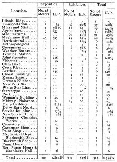
R. H. Pierce, the electrical engineer of the exposition, and L. S. Boggs, the assistant engineer for electrical power, have prepared a table showing the number, distribution and capacity of the electric motors in the service plant at the World's Fair. This table, which gives an excellent idea of the extended use of electrically transmitted power at Jackson Park, is given below:
As will be seen, 315 motors, with an aggregate capacity horse power, are connected with the exposition This does not include the large number of motors in electricity building for which the exhibitors themselves supply current from machinery hall, and which are not operated by the Exposition company. The following is a list of the names of the different varieties of motors operated on exposition circuits: Eddy, Crocker-Wheeler Edison, Thomson-Houston, Diehl, Lundell, Jenney, Westinghouse, Perret, Sprague, Sperry, Card, Ford & Washburn, Keystone, Dunderdale, Eickemeyer, C. & C., Holtzer-Cabot, Western Electric, Kester, Wagner, Detroit, Mather, Emerson, Mayo, Waddell-Entz, Brush, by engineers will Simpson.
Additional details in relation to the elevated electric railway plant at the World's Fair are always interesting, and so no apology is necessary for supplementing the general articles on the road that have appeared in this journal further particulars. Electrical find the sectional drawing of the 1500 kilowatt generator in the power house, Fig. 4, of particular interest. The machine has twelve poles, is compound wound, and is carefully insulated from the ground. The air space between the faces of the poles and the face of the armature is 7-16 of an inch. The armature is built up of sheet iron punchings set around a spider shrunk on the hub. The outer face of the spider is slotted as are the inner faces of the armature punchings, so that they dove tail together. Each circle of sheet iron is carefully insulated from the preceding one, except at one point, and this results in giving to the armature a spiral construction. Not less than 17,200 pieces of sheet iron, weighing 25 tons, were used to build up the nine sheet iron sections, separated from each other by eight brass open rings, resembling spoked wheels, which serve for ventilating purposes. Two four ton cast iron washers held together by bolts, complete the material composing the armature core. The winding of the armature consists of copper strips 34 inches wide by inch thick, two turns to the coil. These are carefully insulated from each other by mica, and each couple is inserted in one of the 348 slots in the laminated armature body each of which is itself lined with a mica tube. The strips are held in place by means of a wooden wedge. The side connections are then riveted and soldered to the strips and are brought down to the massive copper commutator. There are twelve brushes, which are manipulated by of a hand wheel actuating a gearing concealed beneath the floor of the power house. The switchboard, Fig. 5, is made of enameled slate framed in mahogany, and is a striking feature in the installation. It is composed of five panels, one for each machine, each panel containing all the instruments necessary for the control of the machine to which it belongs, i. e., triple pole switches, shunt rheostats, ammeters, automatic circuit breakers, lightning arresters, lightning switches, etc. The circuit breakers are of the new design of the General Electric company, and are provided with automatic resetting devices which close them electrically. With this electrical reset, all or any desired number of circuit breakers in the station can be reset at once. The generators are adjusted so to run in perfect harmony as exactly to divide the load in proportion to their relative capacities — a nice problem with generators of such varied sizes and types. The transportation service effected by trains running at four minute intervals, each train consisting of a motor car and three trailers; the trains weighing means 63 tons each, seating 280 people and the cars being of the same length as those generally used on elevated roads — about forty-five feet from end to end. The weight of these trains, as compared with a train drawn in the usual way by a locomotive, shows a saving of about 20 tons dead weight. The motor cars are equipped with four General Electric motors of the single reduction four pole type, one on each axle. These machines, one of which is shown in Fig. 6, are the most powerful railway motors yet constructed, developing 133 horse power each. They are geared for a speed of 30 miles an hour. Current is taken the conductor rails by means of a sliding shoe contact, Fig. 7. The motors are controlled by a series parallel controller of special type, operated by an ingenious compressed air mechanism. The motors are connected up in a novel way. When the car is started the four motors are in series, then two in series and two short-circuited then, from then the four in series of two pairs of motors each in multiple, two in multiple and two short-circuited and finally all in multiple. By this method the trains are started smoothly and without jerk, and the speed is imperceptibly increased. Air is furnished to the controller and to the air brakes, which are fitted to each train, by an air compressor pump, similar to that used on locomotives, but operated by an electric motor.