Nikola Tesla Articles
A Fully Functional Tesla Turbine Test Stand
A Need for Steam
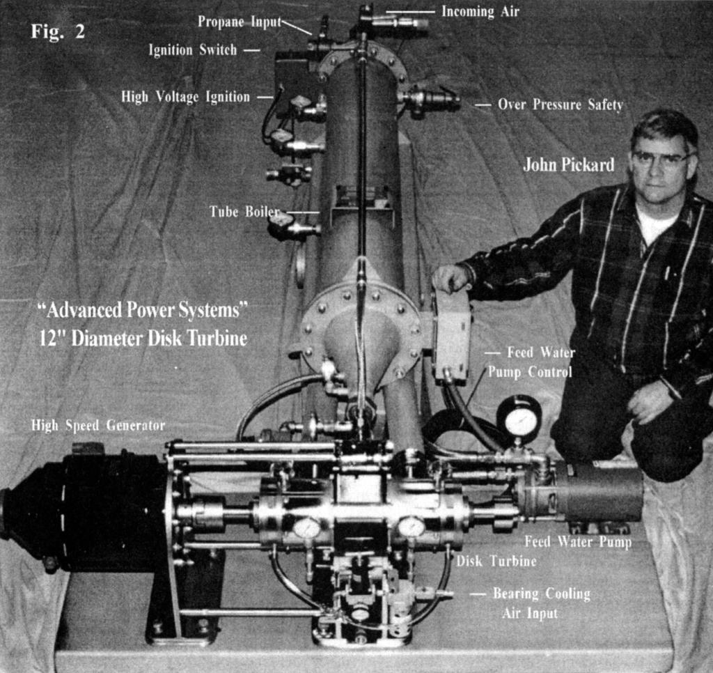
One of the biggest difficulties in the operation and testing of a steam turbine is the availability of testing facilities. It may be possible to find a location where steam power is available but there is typically no way to properly load the turbine. Conversely, a facility may be found that has the capability of providing the required load but then there is no steam supply. This was the dilemma faced by John Pickard after the construction of several different Tesla type, bladeless disk turbines. Toward the resolution of this problem a project was embarked upon, now complete, assembling a complete test stand employing both load and steam supply.
The purpose of the machinery is to investigate the possibility of driving a Tesla turbine in a unique configuration for a possible application existing in New York City. One of the requirements was for the gas pressure to be less than eleven pounds per square inch. Most turbines have very high gas pressures. If the gas pressures are higher, it is a regulatory requirement to have a full time technician on duty.
The reason a low pressure system is being investigated is because there are many apartment buildings in New York City which are supplied by steam, via an old central steam distribution infrastructure that dates back to when Tesla was doing testing at the Edison Waterside Station. The Edison utility has advised the apartment building owners that sometime in the year 2,000 they are discontinuing their steam supply, abandoning the maintenance of the steam infrastructure. The apartment building owners are therefore being forced to find new ways to heat their buildings.
There is also a demand for electric power, as it is very expensive on the east coast. The idea was to produce hot water and steam with a turbine genset, thus allowing production of electricity in small packages while providing for a building's heating requirements.
The boiler is not very efficient in this unit because it is small and therefore a compromise, but it does provide high pressure steam, allowing the establishment of a performance base line for the turbine. The New York project could be successful with properly designed heat exchangers and steam generating components.
Operational Configuration of the Turbine Test Stand
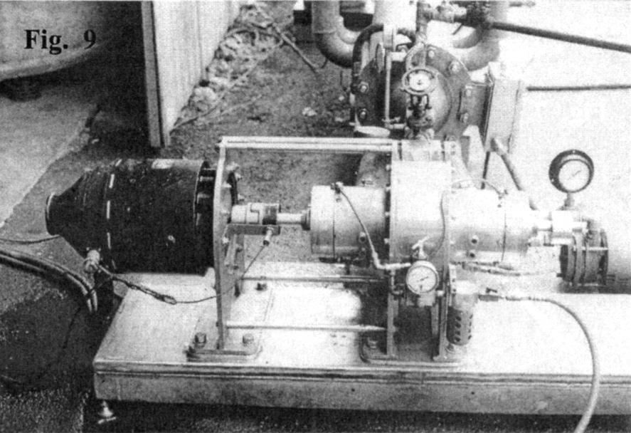
The generator on this unit is a surplus high speed B52 aircraft unit, operated at only 11,000 rpm for safety reasons, though the turbine can operate safely at much higher speeds. Optimal turbine speed is approximately 18,500 rpm. This R&D unit is a "combined cycle" turbine that incorporates a central low pressure runner section, fed directly by combustion waste gases, as well as dual high pressure steam input sections, at each side of the runner.
Following is a brief explanation of the operational configuration of the turbine test stand.
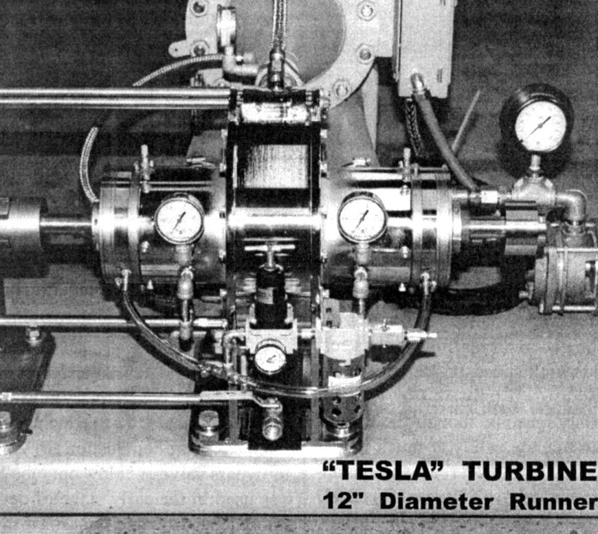
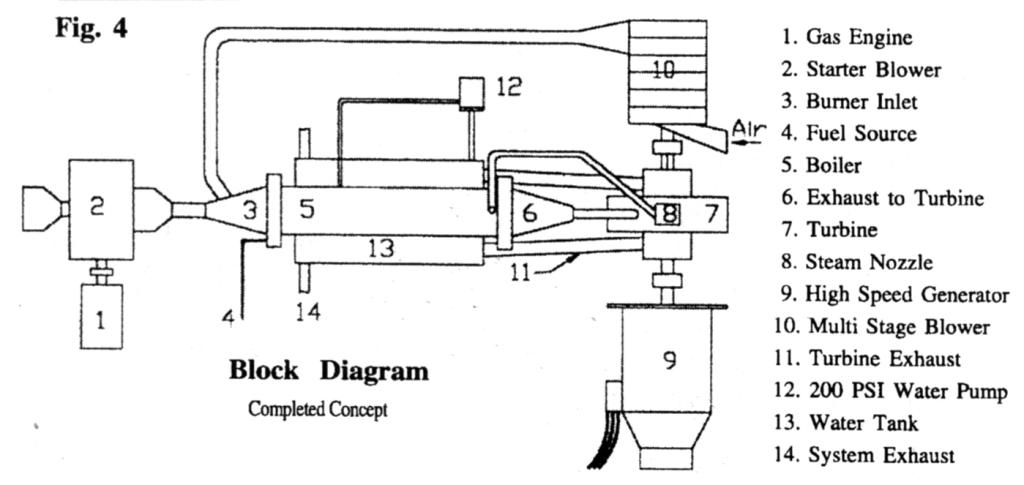
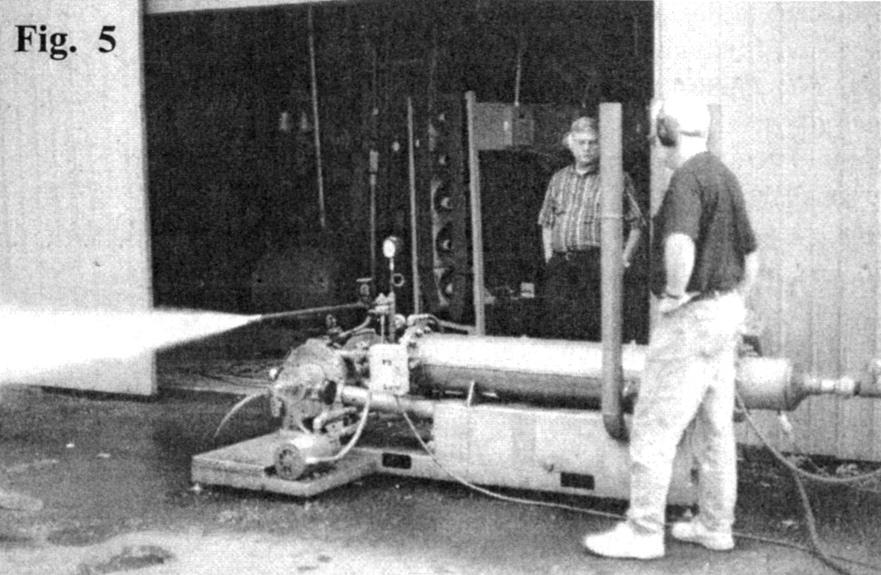
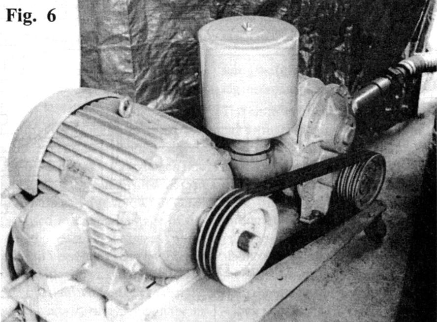
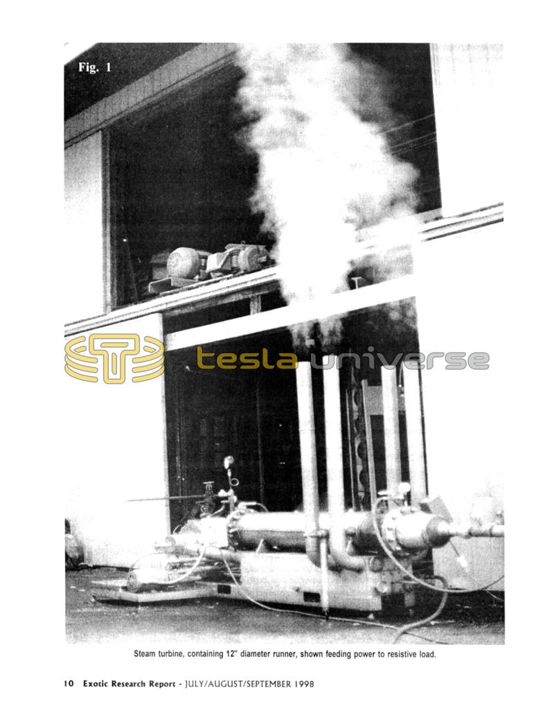
The first component, as tested, is a positive displacement rotary blower (Fig 6) connected to a two inch line that feeds in the combustion air. An air bypass valve or "blow out tube" was used in the early stage of development. It would bypass air in order to be able to start the burner without blowing out the flame. The bugs are now worked out so that the burner starts instantly without the air bypass requirement. Note the pressure gage (visible in Fig 1 &5) for reading incoming pneumatic pressure.
The air inlet is connected to a conical diffuser section that slows the velocity and increases pressure. A stainless steel flange connects this diffuser to the burner manifold. A feed line supplies propane gas through this flange into the burner jets. A gage is visible above the stainless steel flange which indicates the propane fuel pressure. Beyond this flange is the burner section which contains a high temperature ceramic refractory lining.
Adjacent to this area, mounted to one side, is a high voltage ignition box, containing a spark coil and ignition switch. A wire connects from this box to a spark plug protruding through the burner housing wall.
The next section is a duct tube coil boiler. It uses about 120 feet of coiled tube, 1/2" schedule 40 steel pipe. The main burner tube is eight inches in diameter. There are two jacked cavities beyond the main inside barrel.
The unit employs a 2 hp, three phase, 220 volt 3,450 rpm boiler feed water pump, supplying ten gallons per minute flow @ 200 psi. The feed water pump gets its water from the large tank structure under the tube boiler. This pedestal base serves four purposes: It supports the burner/boiler; is a water reservoir for the steam boiler; acts as a muffler; and heat exchanger.
Water that feeds the reservoir tank, which is the input for the feed water pump, at atmosphere, is just city water. The only treatment is accomplished by passing the water through an allotropic water treatment cell. This cell changes the molecular polarity of the minerals in the water so that they will not adhere to the components of the boiler tubes and turbine.
The feed water pump takes water from the tank and feeds the outer jacket of the tube boiler. The water then transfers through a hole to the inner jacket, thus preheating the water before it is fed to the boiler coils.
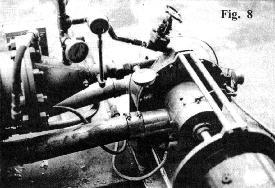
The steam coils are wrapped around a flame several feet long, generated by the burner. The burner exhaust does not go directly to atmosphere, as in a conventional steam tube boiler, but travels through a cone at the end of the tube. This then feeds into a 1-1/2 inch pipe supplying the "low pressure," center section, of the turbine runner (see photos). To prevent excessive back pressure, wider disk spaces are employed in the 1-1/2 inch central portion of the turbine runner which is fed by the output of the combustor.
The turbine runner is a total of 4 inches wide. The outer 1 inch sections of the runner are constructed using narrower disks and spacers and are fed with high pressure steam from the steam coil output. The end disks on each side of the runner are 1/4 inch thick. The center runner section employs .06 inch disks and spacing, while the high pressure outer sections of the runner use .03 inch thick disks and .03 inch spacings. The next issue, #15, of the Tesla Engine Builders Association (TEBA) newsletter will contain photographs detailing the turbine's internal construction.
There is a pressure gage at the low pressure inlet to the turbine (output of the burner). It indicates approximately 8 psi when the turbine is running. It is interesting to note that the turbine will operate and produce several horsepower using only the output of the low pressure burner section which provides just 8 psi of inlet pressure to the turbine.
There is also a temperature gage at the low pressure turbine input. The gas temperature, after giving up some of its heat to the steam coils, has been operated as high as 1,200°F without damage to the turbine. It is usually run, however, at between 750-800°F.
The coils contained in the steam generator produce 180 psi or more of pressure and absorb approximately 1,000°F of available heat so only about 1,000-1,200°F maximum temperature is applied to the center, low pressure section, of the turbine runner.
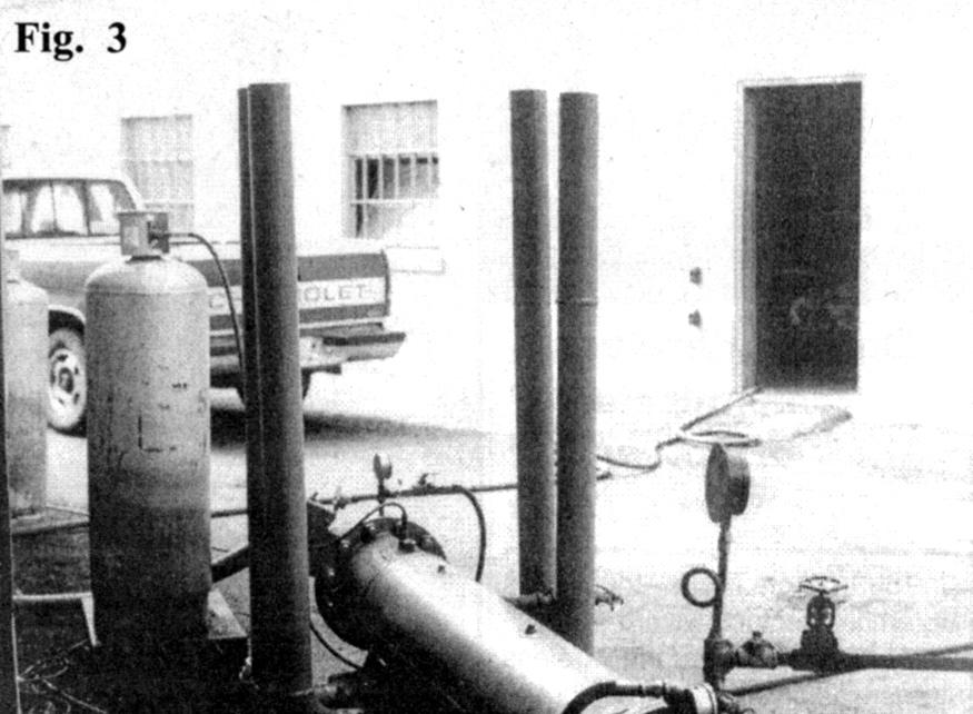
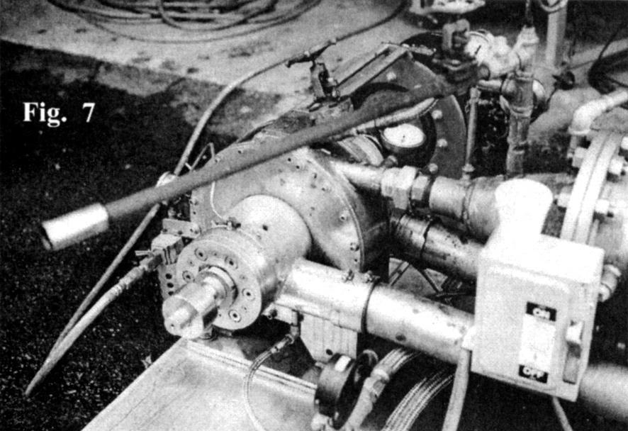
Sonny Entrican, President of Entrican Vacuum Products, where this turbine was tested, has developed a very good technique for operation of the boiler. It involves the steam bypass tube pictured in Fig 7. First the feed water pump master switch is engaged, drawing water from the reservoir through the steam coils. Instead of the output of the steam coils feeding the turbine, the steam coil output bypasses the turbine, using valves, into the protruding pipe to atmosphere. Enough water is allowed to flow through the steam tubes and out the bypass pipe to expel all of the air in the system. After the air has been expelled and water is flowing freely the ignition switch is thrown, activating the spark plug. The main air is turned on (Fig. 6) and then the propane valve is opened.
Within just two minutes time, dry, invisible, superheated steam, at approximately 300°F is at the output of the bypass pipe. Running the burner harder, it has been possible to produce 600°F steam. The turbine input valve is then opened and the bypass valve closed, just before the steam becomes invisible (Fig. 5).
Note the nozzle mounted at the end of the steam bypass pipe discharge. It is a diverging type nozzle simulating the nozzles contained in the turbine. The high pressure steam feeds a hollowed out block, on the top of the turbine, which directs the steam to similar diverging type nozzles, directed at each of the two high pressure runner sections.
The rotor and shaft of the turbine weighs approximately 100 lbs. There is a 25 lb armature in the generator, for a total of 125 lbs of rotating mass. Speed is determined by a photo tachometer pickup, mounted at the generator side of the turbine, reading pulses from a white piece of reflective tape.
There are two bearings at each side of the turbine. They are very high quality, class 7, high speed angular contact bearings. The shaft turns very freely. An air line and regulator at the front side of the turbine provides air cooling to each of the bearing housings. The heated air exits to atmosphere through a hole at the bottom of each housing.
The turbine pedestal base is constructed from 1" thick carbon steel, overlaid with stainless steel to prevent corrosion. The generator is attached to a carbon steel mounting plate that has been nickel plated. The turbine housing has also been nickel plated. The support struts between the generator and turbine are all exactly the same length and provide for perfect alignment of the couplings.
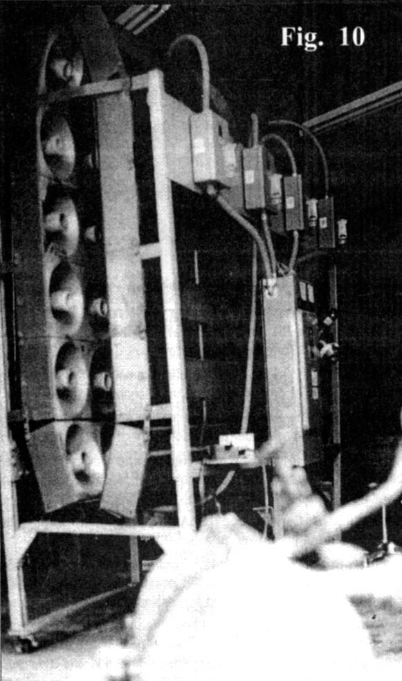
The cables from the generator feed power to a resistive load bank. Generator electrical load is adjusted with a control which varies the field current. The load bank contains a main switch panel with voltage and current meters. There are four separate distribution switches allowing the load to be brought in 25% at a time. The load array consists of ninety six, 750 watt, ceramic/tungsten heating elements. The load array is therefore capable of approximately 100 hp of continuous dissipation.
The steam and hot gases exit the turbine via dual exhaust, three inch channels. Each exhaust output contains a spray nozzle, spraying water pressurized by the feed water pump into the exhaust gases for heat recovery. It must then pass through two stainless steel filter screens. What does not give back its heat and condense in the water tank goes out the exhaust stacks. The output temperature of the exhaust stack is only about 170°F.
Efficiency?
The thermal efficiency, as far as heat in versus heat out, is very good. The efficiency, as far as mechanical power, is mainly at the expense of the boiler, which is much too small to provide the power required. If the boiler was 4 or 5 times larger then it would be up in a very competitive efficiency range.
Electrical output power is determined by multiplying the volts by amperes from the generator and dividing by 746 to determine hp. The measured power consumption of the rotary compressor and water feed pump motors is then subtracted from this number. The fuel consumed in pounds is converted to available hp. Efficiencies can then be approximated. No allowance was made for generator inefficiency.
Total thermal efficiencies, on this basis, have been determined to be approximately 8% due to the low efficiency of the steam boiler. The conversion efficiency of the turbine was, however, calculated to be in the high 30s, very similar to the single stage turbine efficiencies determined by Tesla.
More information on efficiencies and the internal construction of the turbine will be presented in the next issue of TEBA News.
A Vital Detail
One very important construction detail, determined vital for turbine efficiency, is a drain hole machined into the bottom of the turbine case ring. If not used, water will accumulate in the case ring and flood the runner. This flooding effect parasitically loads the turbine, destroying the efficiency.
After this problem was discovered, a 3/4 inch hole was drilled and tapped into the bottom of the case ring and a pipe and valve attached. It was discovered that when the valve was left open, during operation, that there was insignificant pressure loss through the open hole. The working fluid had already fully entered the disks before it could reach the drain hole, located on the opposite side of the case ring, so pressure loss does not occur.
The working fluid essentially enters the disks almost immediately after leaving the nozzle. This drain hole is a very necessary item and must have been used by Tesla as he employed saturated steam. This explains why very poor efficiencies have been experienced by others in the past while attempting operation with steam.
Future Plans...
It is Advanced Power's desire to sell this equipment to further the research. They will consult with the buyer if desired to take it to the next level of development.
Advanced Power and Entrican Vacuum Products have proven that the Tesla turbine can be made to do work. It is up and running and improving total package efficiencies is simply a matter of better heat exchangers and a more efficient boiler.
By visiting the Tesla Engine Builders Association web site at:
www.execpc.com/~teba
much more can be learned about the Tesla turbine.
