Nikola Tesla Articles
John Cooper III Experiments with Tesla Coil
Source:
E-mail correspondence from John Cooper III
Contact:
John Cooper III, [email protected]
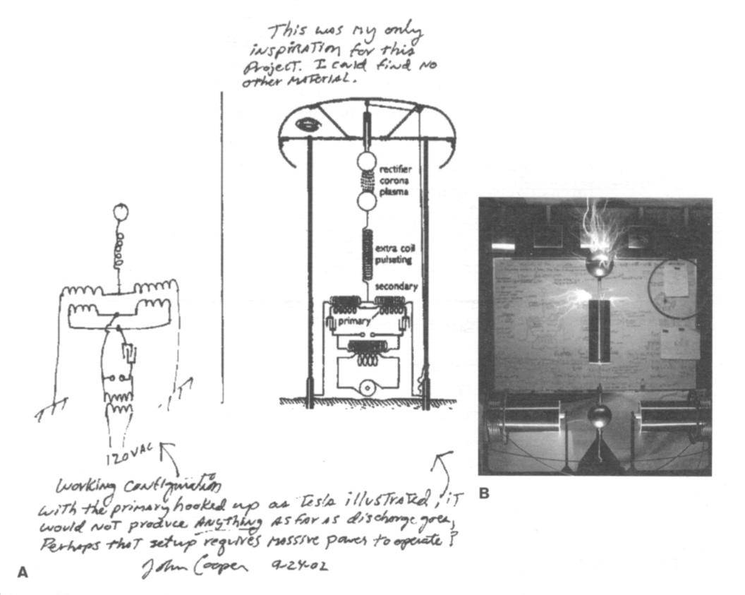
John Cooper III, using a schematic of Tesla's oscillating statically-charged terminal previously featured in ESJ (35:7), has constructed the apparatus, calling it a two-phase magnifier. (See Fig. 1a.) It is part of the workings proposed for the Wardenclyffe tower. The primary and driver coil on the left are wound counterclockwise, with the right side wound clockwise. It is powered by an unpotted 9 kV, 120 ma neon sign transformer and a custom 0.035 mf capacitor. The top of the sphere, measuring a little over 5 feet across in diameter, is 6.5 feet from the floor.
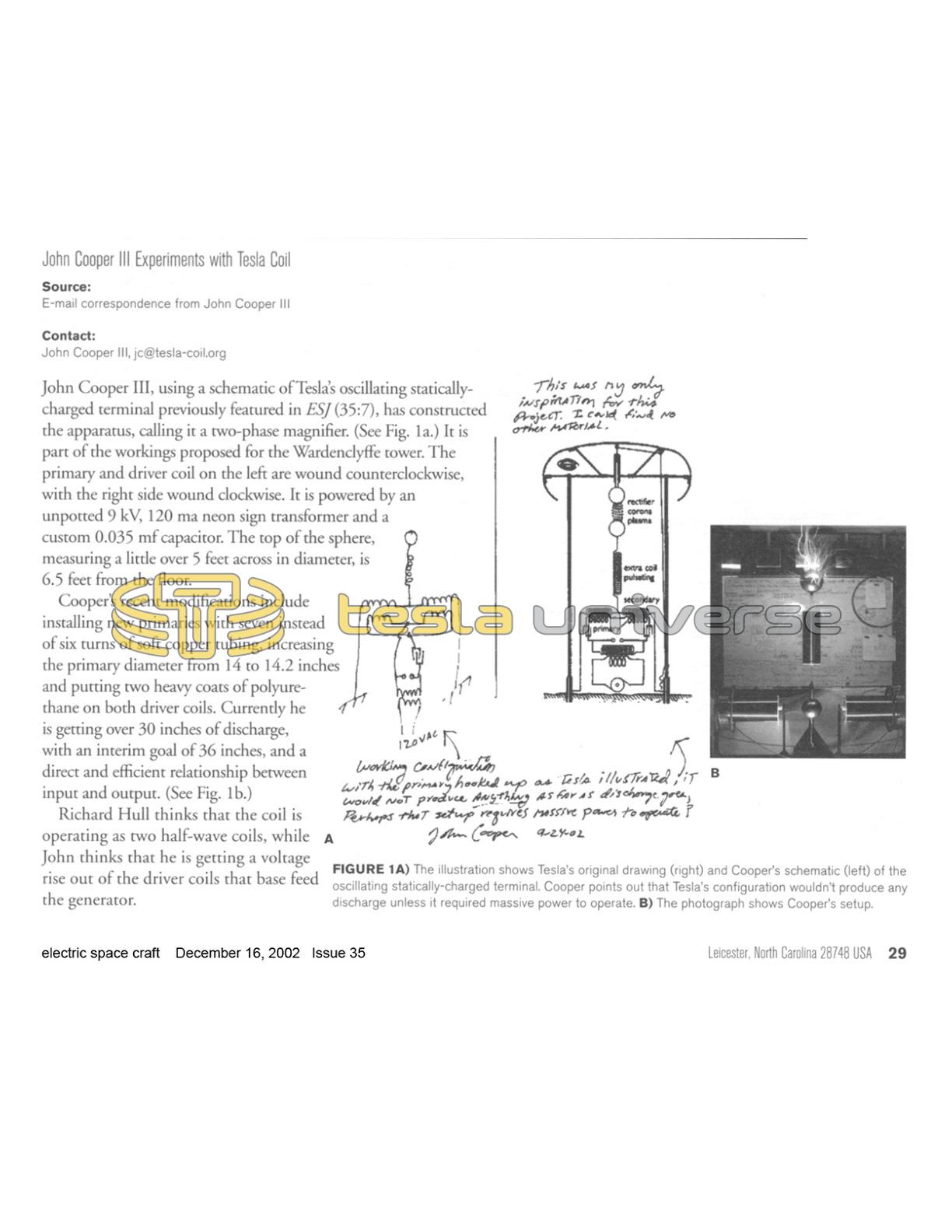
Cooper's recent modifications include installing new primaries with seven instead of six turns of soft copper tubing, increasing the primary diameter from 14 to 14.2 inches and putting two heavy coats of polyurethane on both driver coils. Currently he is getting over 30 inches of discharge, with an interim goal of 36 inches, and a direct and efficient relationship between input and output. (See Fig. 1b.)
Richard Hull thinks that the coil is operating as two half-wave coils, while John thinks that he is getting a voltage rise out of the driver coils that base feed the generator.