Nikola Tesla Articles
Goodness, Q and Power Factor in Electrical Science and Machinery
"The criterion of ‘good design' of all electrical machines is expressed by a constant...which gives a measure of the effective utilization of...space for the transformation of energy."
Gabriel Kron, 19301
Abstract - After briefly highlighting the professional career of Dr. Eric Laithwaite, we turn to his intuitively obtained notion of "Goodness" as a physical parameter and demonstrate that it can be deduced from Maxwell's equations. Goodness is linked to the parallel concepts of Q and power factor, and related to machine efficiency. Examples of cosmic "Goodness" are discussed. Finally, negative resistance via regeneration and parametric regeneration is introduced as a practical means to accomplish "Hyper-Goodness."
I. Introduction
This paper has several goals. First we wish to illustrate the link between Eric Laithwaite's "Goodness factor," Gabriel Kron's criterion of good design (which measures the effective utilization of space), the circuit quality factor known as Q, and electrical power factor. Second, we provide a generalized derivation of Laithwaite's Goodness directly from Maxwell's equations. And, finally, we describe how parametric operation can be used to provide "Hyper-Goodness."
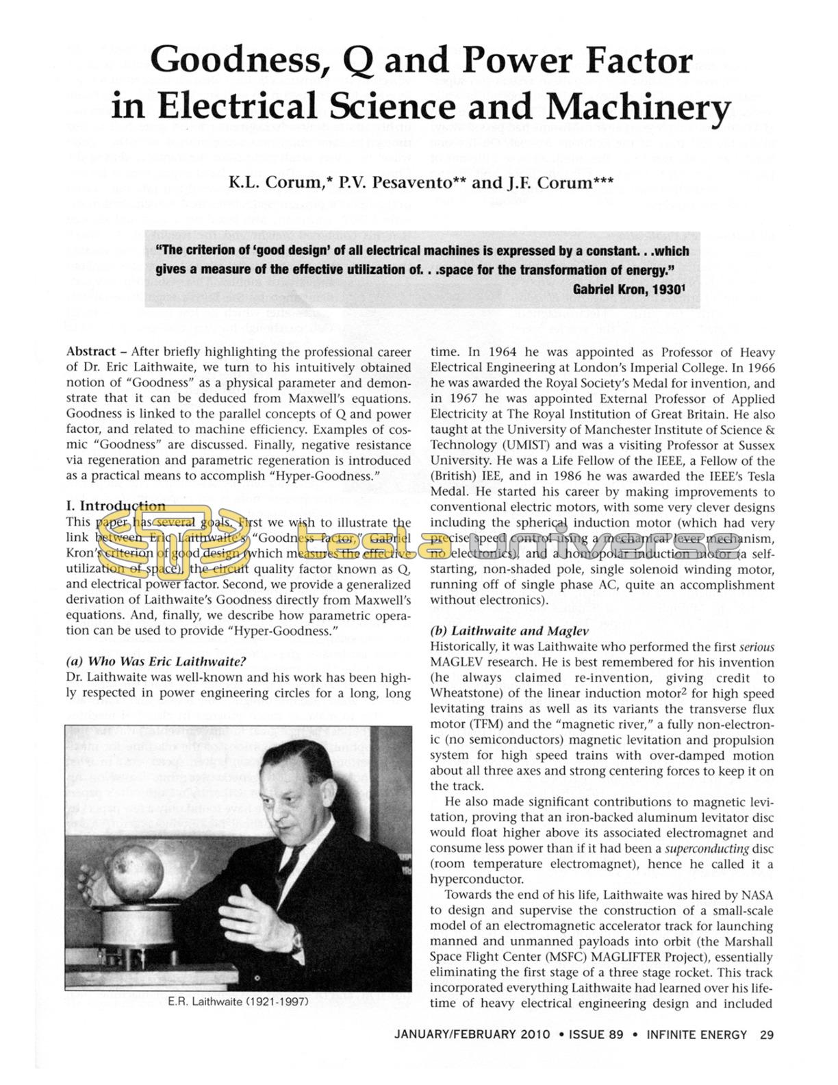
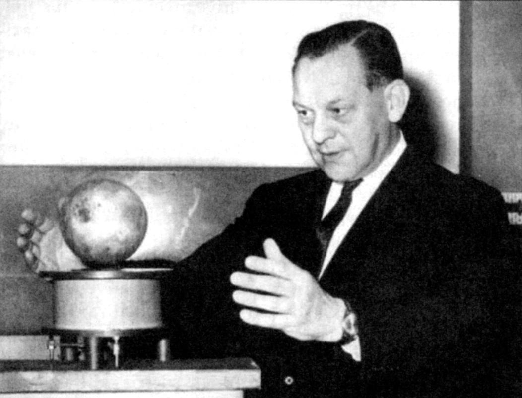
(a) Who Was Eric Laithwaite?
Dr. Laithwaite was well-known and his work has been highly respected in power engineering circles for a long, long time. In 1964 he was appointed as Professor of Heavy Electrical Engineering at London's Imperial College. In 1966 he was awarded the Royal Society's Medal for invention, and in 1967 he was appointed External Professor of Applied Electricity at The Royal Institution of Great Britain. He also taught at the University of Manchester Institute of Science & Technology (UMIST) and was a visiting Professor at Sussex University. He was a Life Fellow of the IEEE, a Fellow of the (British) IEE, and in 1986 he was awarded the IEEE's Tesla Medal. He started his career by making improvements to conventional electric motors, with some very clever designs including the spherical induction motor (which had very precise speed control using a mechanical lever mechanism, no electronics), and a homopolar induction motor (a self-starting, non-shaded pole, single solenoid winding motor, running off of single phase AC, quite an accomplishment without electronics).
(b) Laithwaite and Maglev
Historically, it was Laithwaite who performed the first serious MAGLEV research. He is best remembered for his invention (he always claimed re-invention, giving credit to Wheatstone) of the linear induction motor2 for high speed levitating trains as well as its variants the transverse flux motor (TFM) and the "magnetic river," a fully non-electronic (no semiconductors) magnetic levitation and propulsion system for high speed trains with over-damped motion about all three axes and strong centering forces to keep it on the track.
He also made significant contributions to magnetic levitation, proving that an iron-backed aluminum levitator disc would float higher above its associated electromagnet and consume less power than if it had been a superconducting disc (room temperature electromagnet), hence he called it a hyperconductor.
Towards the end of his life, Laithwaite was hired by NASA to design and supervise the construction of a small-scale model of an electromagnetic accelerator track for launching manned and unmanned payloads into orbit (the Marshall Space Flight Center (MSFC) MAGLIFTER Project), essentially eliminating the first stage of a three stage rocket. This track incorporated everything Laithwaite had learned over his lifetime of heavy electrical engineering design and included many counterintuitive details like very large air-gap surface windings, instead of the usual windings in slots, and a full magnetic river levitation and propulsion system (no superconductors). Two of the authors had the opportunity while working on a subcontract for the MAGLIFTER project out of MSFC (this was a few years after Laithwaite had passed away) to see the test track at the Redstone Arsenal. On the one hand it was a pleasure to see the culmination of a lifetime of Laithwaite's cunning handiwork in one place, and on the other it was sad that further research on this promising concept was later canceled.
(c) Laithwaite's Publications
Being an educator at heart, Laithwaite wrote numerous peer-reviewed journal articles, engineering textbooks, and even children's books on science. He also wrote a collection of articles for the magazine Electrical Review with the title "Electromagnetic Phenomena." Subtitles of the articles were: The Shape of an Electric Current; How the Low Speed Brushless AC Motor Was Invented; The Bigger the Better; The Smaller the Better; Rack and Pinion Motors; How an Experiment with Iron Filings Provided New Motor Design Information; The Key to the Cosmos; Mini-Magnets and Micro-Magnets; More About the Jumping Ring; The Parallel World: Is It Inevitable?; Poles or Circuits: A New Concept in Magnetism; Of Teapots and Electric Motors; The Evolution of a Three Dimensional Electric Motor; Electromagnetic Rivers for High Speed Transport; The Rules of Planet Earth; The Rules of Men; The Rules of God; The Strange Happening at Savoy Place; The One That Got Away; The Quick and the Dead; Superconductivity and the Midas Touch; The Hyperconductor and the Linomat; The Shape of Things to Come; The Multiplication of Bananas and Umbrellas; The Bigger They Are the Harder They Fall; 1975: A Space Odyssey; 2001: Learning in Parallel; The Impossible Dream; Electromagnetism Is a Whodunit; All Things Are Possible; The Continuing Story of Gyroscopic Magic.
In these articles, Laithwaite used the forum to discuss what is wrong with engineering education, what is wrong with government funding of research (you know he's headed for troubles with university administrators with that one), as well as giving details of his linear motor and magnetic levitation work, including the infamous "gyroscope episode" (see the following paragraph). Electrical Review posted an advertisement in its pages in 1976 that it was going to soon re-publish all of these articles in a single volume, but failed to do so even after 15 years (which is when one of us contacted them about it). The series ran over a four year period from 1972 through 1975. A Laithwaite bibliography was prepared several years ago by Valone.3
(d) Laithwaite and Gyroscopes
In the mid-1970s, Laithwaite was asked to present a couple of lectures at the Royal Institution in London: one for the Friday Evening Discourses in 1973 and the other for the famous Faraday Christmas Lectures in 1974, where in both instances he demonstrated what appeared to be a reduction in the weight of a pair of counter rotating motorcycle wheels on a common shaft. The wheels [whose total dead weight was over 50 pounds in the first lecture, 16 pounds (a single wheel) in the Christmas lecture] were on the end of a three foot handle. When spun up with an electric drill, they could easily be lifted over his head with one hand. (Laithwaite was in his 50's and already beginning to be quite frail at this time.) The same thing was accomplished with the lighter wheel by a very small child from the audience during the Christmas lecture. (This child's facial expression, as he was able to effortlessly lift the heavy weight, is priceless.) Later, in the BBC TV program series "Heretics" (which aired in the early 1980s), Laithwaite also stood on a scale and showed that his combined weight and the weight of the wheel decreased when the gyro wheel was spun up. He asserted that this appeared to contradict what Newton taught about the laws of motion. This resulted in his condemnation by the British scientific establishment - after which he lost tenure at Imperial College (though Imperial College continued to list him as a Professor Emeritus well into the 1990s). The Royal Institution refused to let the BBC broadcast the Friday Evening Discourse Lecture, which had been videotaped. (It was later re-enacted in "Heretics" program.) The controversy has continued to today, with a "deeper assessment" made by a summer student in the Breakthrough Propulsion Physics office at NASA,4,5 and a 2006 debunking of that assessment by Solomon.6 The subject of the present note is not propulsion physics, but rather classical electrical machinery and what Laithwaite called the "Goodness factor," which certainly is not a controversial topic.
(e) What Is the Goodness Factor?
In 1965 Laithwaite derived (apparently by inspection) an equation for designing optimized electrical machines, which he called the "Goodness factor." This equation was, almost simultaneously, derived by several Russian researchers (to whom Laithwaite gives credit in one of his books7) who called it the "Electromagnetic Reynolds Number." Even earlier, Gabriel Kron (back in 1930) had derived a similar equation for "good machine design." One reason that Laithwaite was able to make so much progress in electrical machine design (besides being a great intuitive inventor) was his ability to optimize the proportions of the machine for maximum performance (efficiency, power, speed, etc.) in what would now be called a "genetic algorithm" based on his "Goodness factor" equation. Other than Laithwaite's papers and books on the topic, we have found only a few papers by other authors in English about his Goodness factor,8 a surprising result. Laithwaite's "genetic algorithm" was only derived for J x B machines.
Few of the modern electromagnetics textbooks appreciate the practical importance of the Maxwell stress tensor for machine analysis and design, especially in the lossy material case where there is almost no viable alternative for calculating machine forces. (The principle of virtual work fails in dissipative media.9) There are four Maxwell Stress Tensor machines: B2 per unit area (magnetic machines); J x B machines (electromagnetic machines, such as the conventional AC and DC motors and generators); ρE machines such as the Franklin/Pogendorff/Jefimenko electrostatic machines; and Slepian/Heaviside d/dt (D x B) machines (the Maxwell Stress Tensor Space Drive).
What we will show in this paper is that, instead of a derivation by inspection (as Laithwaite did), one may formally deduce Goodness directly from Maxwell's equations. It will then appear in a more generalized form, which may be applicable to other stress tensor machines.
Laithwaite generalized the notion to a mechanical Goodness factor for gyro wheel design, and claimed that it was critical to getting maximum performance from spinning objects.
II. Generalized Electromagnetic Machine
We start with some basic questions. First, what is an electric circuit? Paris and Hurd provide a satisfying description, "A circuit is a configuration of electromagnetic structures which allow specialized fields to exist in confined regions of space."10 As pointed out in a previous publication, lumped element circuit theory assumes that there are no wave interference phenomena present, that is, the current entering and leaving the circuit element's terminals are identical. (1. The current distribution function is spatially uniform across each element. 2. The spatial phase delay between circuit extremities is zero.)11
And, now we ask, what constitutes an electrical machine? (And, what bounds has nature placed upon it?) Laithwaite answered the first of these as follows: "It might be defined as a device for transferring power from one location to another across space."12
This unsubstantial phantom beggars the mind. To grasp the notion requires something with form. Poets do such things:
And as imagination bodies forth
The forms of things unknown, the poet's pen
Turns them to shapes and gives to airy nothing
A local habitation and a name.13
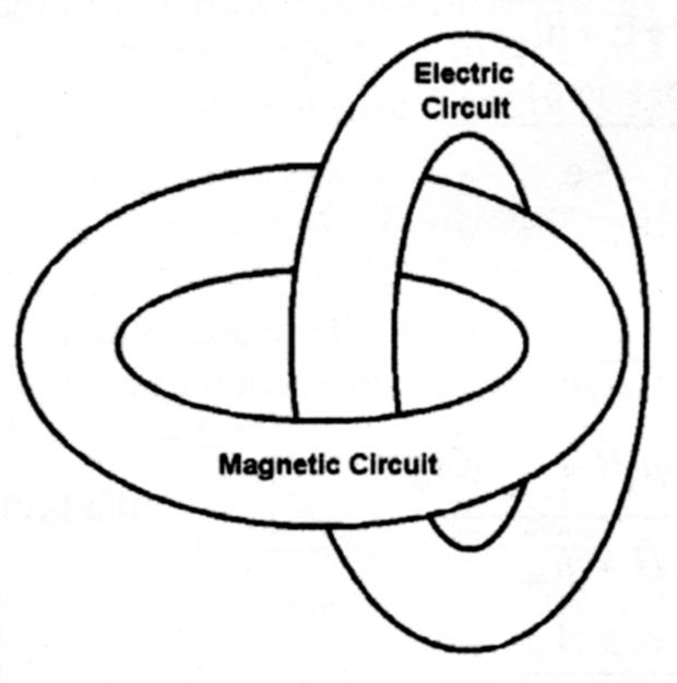
But, can the pen of engineers body forth such things too? Laithwaite proceeds to sketch his fundamental machine as an almost mystical (but mathematical) union of dual, multiply-connected topologies. See Figure 1. Like Theseus of old, Laithwaite, too, has bodied forth from airy nothings the forms of things unseen. Laithwaite's cunning imagination blossomed into the following description:
Viewed in the most fundamental way, every motor is no more than a magnetic circuit and an electric circuit linked together.14
He expands on this notion of coupled rings by adding the caveat,
The magnetic circuit must contain an air gap in any machine in which mechanical movement is required. (A transformer is an example of an electrical machine with no moving parts and a completely closed magnetic circuit.)
Laithwaite's "simplest" form of an electrical machine is actually a transformer. (Recall Steinmetz's old description, "The induction motor is a specialization of the general AC transformer."15)
Laithwaite then asserts,
...there is no more generalized form of an electrical machine than two loops interlinked as shown in Fig. 2 [Figure 1 herein]. In addition, there may be need for motion if mechanical power is involved in the interchange, and one or the other of the loops may need to be broken and remade repeatedly. This necessitates changes in the shape of the structure...but which does not effect the overall principle.16
According to Laithwaite, "...[this is] a structure which is fundamentally as simple as possible...Unfortunately it does not appear to be possible to distribute both circuits around one another simultaneously."17
A structure bearing a striking resemblance to Laithwaite's fundamental machine was once proposed for ball lightning.18 (In our ball lightning research we documented no glowing toroids.19) The notion of linked fields, of course, goes back at least to the minds of Faraday and Maxwell.
III. Heuristic Derivation of Goodness
And now we get a glimpse of the soul of an engineering genius at work. Laithwaite's intention was to penetrate the fundamental issues and distill some universal parameter for characterizing the performance of all electrical machinery. This is how the notion of "Goodness" was birthed into existence.
In what he called his "most important paper,"20 Laithwaite21,22 reasoned that the electric path was degraded by resistance. The wire path resistance (an opposition to passing current) can be expressed as:
$$R=\frac{EMF}{I}=\frac{\ell_e}{\sigma A_e}=\frac{\rho \ell_e}{A_e} \; \; ohms \; \; (1)$$
where \(\ell_e\) is the electrical path length, σ is the electrical conductivity, Ae is the cross-section of the electrical path, and ρ is the electrical resistivity.
Similarly, the magnetic path is degraded by reluctance. The flux path reluctance (an opposition to setting up flux) is expressed by
$$\mathcal{R}=\frac{MMF}{Flux}=\frac{\ell_m}{\mu A_m} \; \; rels \; \; (2)$$
where \(\ell_m\) is the magnetic path length, u is the magnetic permeability, and Am is the cross-section of the electrical path. (Note that series reluctances add like series resistors.)
Laithwaite reasoned that, "Since we seek to produce a force in a machine, and force is proportional to the product of current and flux, J x B, the product of resistance [opposition to the passage of current] and reluctance [opposition to the formation of magnetic flux] must represent badness."23 How good a machine is (call it "Goodness") is the reciprocal to the machine's "badness." As a result, Laithwaite tries the expression
$$Goodness = \frac{1}{Badness} = \frac{1}{R \times \mathcal{R}} \; \; (3)$$
This expression has the dimensions of seconds. Laithwaite recognized that something is still missing and illogical: the units aren't dimensionless, as one would expect.
It has been said that a true artist "...mixes his brains with his colors; and when he dips his brush into the paint he lays it onto the canvas with his soul...It is not the color, but the man's heart that has got out onto the canvas. That is real painting."24 With Laithwaite, we see something of his soul in this derivation. He surmised that (for an AC machine) the constant of proportionality that makes the units dimensionless is angular frequency, ω. [It would be an equivalent velocity-dependent quantity for a DC machine.] Following this thread, Laithwaite then obtains the structure's Goodness as the product
$$ \Gamma = \frac{1}{R} \times \frac{1}{\mathcal{R}} \times \omega = \frac{\omega \mu \sigma A_e A_m}{\ell_e \ell_m} \; \; (4)$$
This is Laithwaite's "Goodness factor" for an AC machine. [In order to avoid confusion with the symbol for electrical conductance (G = 1/R), we are using the symbol Γ for Laithwaite's Goodness factor.] The criterion of goodness is minimized "badness."
Westinghouse pioneer Alfred Schmid once described machine design by saying, "All you have to do is place the metal where it belongs and the machine becomes beautiful of itself."25
Schmid's advice is a lot like the formula for being successful on Wall Street: "buy low and sell high." The advice is correct, but it doesn't tell you how to make critical decisions. However, with Laithwaite's algorithm, we not only have a way to predict a machine's performance before we build it, but we also are given instructions to follow to enhance the design. For example, Equation 4 reveals the effect of increasing a machine's physical size. If the linear dimensions are doubled, then the goodness increases by a factor of four.
Clearly, there is something fundamental going on here. Yet, it is bizarre - almost pathological - why so many critics have attacked Laithwaite, perhaps in an attempt, like Münchausen, to elevate themselves by their own bootstraps.
IV. "Goodness": A Derivation from Maxwell's Equations
We now come to the main purpose of this paper, which is to illustrate how "Goodness" may be derived directly from Maxwell's equations. If "Goodness" really is a fundamental concept, as we feel in our bones, then surely the notion must be obtainable from the Principle of Least Action, or at least contained within invariant expressions like Maxwell's equations or General Relativity.
(a) Problem Formulation
As with the derivation of the Poynting vector, we initiate the manipulations directly from Maxwell's equations. With an eye towards engineering applications and electrical machinery, we utilize the time-harmonic field equations with e+jωt time dependence:
$$\nabla \times \vec{H} = (\sigma + j\omega\varepsilon)\,\vec{E} = "\overset{\small\frown}{y}"\,\vec{E} \; \; (5)$$
$$\nabla \times \vec{E} = - j \omega \mu \vec{H} = - "\overset{\small\frown}{z}"\,\vec{H} \; \; (6)$$
where Harrington26 identifies ŷ and ẑ as the complex admittivity (admittance per unit length) and complex impedivity (impedance per unit length), respectively. (If one supplies the boundary conditions, then the differential form of Maxwell's equations are completely equivalent in content to the integral form of Maxwell's equations.)
In integral form one may write a shunt admittance and series impedance, respectively, as:
$$"Y" = \frac{I}{EMF}$$
\[
\; \; \; = \frac{\iint[\sigma + j\omega\varepsilon]\,\vec{E}\bullet\hat{n}\, dA_e}
{\oint \vec{E}\bullet \vec{dl}_e} \;\;\;\; (7a,b,c)
\]
\[
\;\;\;\;\Rightarrow\;
\frac{(\sigma + j\omega\varepsilon)\,A_e}{\ell_e}
\]
and
\[
Z \;=\; \frac{V}{\text{MMF}}
\]
\[
= \frac{-\iint j\omega\mu\,\vec{H}\bullet\hat{n}\, dA_m}
{\oint \vec{H}\bullet \vec{dl}_m} \;\;\; (8a,b,c)
\]
\[\Rightarrow\;
\frac{j\omega\mu\,A_m}{\ell_m}
\]
where the large arrows indicate taking the limit for geometries with uniform field distributions. These situations are consistent with Harrington's27 observations:
$$ \pmb{Y} = \pmb{y} \frac{\pmb{A}_e}{\ell_e} \;\;\; (9)$$
$$ \pmb{Z} = \pmb{z} \frac{\pmb{A}_m}{\ell_m} \;\;\; (10)$$
which are descriptive of circuit elements with uniform fields. A dimensionless electromagnetic parameter Γ may then be defined by the scalar multiplication ZY:
$$ \Gamma \;=\;
\left|\, \frac{V}{\mathrm{MMF}} \times \frac{I}{\mathrm{EMF}} \,\right| \; \; \; (11) $$
which leads to a generalized "Goodness" expression,
$$ \Gamma \;=\; \left| \frac{j\omega\mu\,(\sigma + j\omega\varepsilon)\,A_e\,A_m
}{\ell_e\,\ell_m}\right| \; \; \; (12) $$
which is fundamental to all electromagnetic devices. This is the sought-after relation. [If the fields are not uniform, Goodness is expressed as the product of Equation 7b times Equation 8b. When the fields are uniform and the medium is homogeneous, this reduces to Equation 12.]
(b) Passage to Conventional Machinery
For the electromagnetic machines having fields that are uniform and with conduction current predominating over displacement current, Equation 12 reduces to Laithwaite's expression for Goodness:
$$ \Gamma \; \Rightarrow \; \frac{\omega \mu \sigma A_e A_m}{\ell_e \ell_m} \; \; \; (13) $$
where the arrow indicates the limit being taken. (When the physical dimensions of the circuit are much, much less than a free-space wavelength, the fields may be considered as uniform over the physical dimensions of the circuit.) Laithwaite observed that, "The best electric circuit passes the greatest current as the result of an applied EMF...the best magnetic circuit produces the greatest flux as the result of an applied MMF..."
This would imply that, for motors and energy conversion devices, the "best" electric machine has the greatest admittance (current per applied EMF) and the best magnetic circuit has the greatest induced voltage per applied MMF. A good machine wastes little energy in its conductors (where power is developed) or in its iron.
In the general case, Equation 12 leads to the relation
$$ Z \times Y \; = \; \left(j \omega \mu \sigma - \omega^2 \mu \varepsilon \right) \frac{A_e A_m}{\ell_e \ell_m} \; \; \; (14) $$
When the fields are uniform over the circuit elements, Maxwell's equations lead directly to the simple relations for R, C, and L,28
$$ L = \frac{\mu A_m}{\ell_m} \; \; \; C =\frac{\varepsilon A_e}{\ell_e} \; \; \; R=\frac{\ell_e}{\omega A_e} \; \; \; (15a,b,c) $$
$$ LC=\frac{1}{\omega_o^2} \; \; \; Q=\frac{\omega_o L}{R} \; \; \; (16a,b) $$
Rewriting Equation 12 with these uniform field expressions gives
$$ \Gamma \; = \; \left| \; -\omega^2 LC + j \frac{\omega L}{R} \; \right| \; = \; \left| \; - \left( \frac{\omega}{\omega_o}\right)^2 + j Q \; \right| \; \; \; (17a,b) $$
In the power mains (low frequency) limit, ω<<ωo, Γ passes to Laithwaite's expression given by Equation 4.
There are two more Maxwell equations. As noted in Section X below, perhaps those will give the long-sought Goodness factor relation for magnetic machines.
V. "Q" - From Maxwell's Equations
Consider a coil-wound inductor of magnetic cross-section Am and magnetic path length lm. Let the wire cross-section be Ae and the wire path length be le Note that from Ampere's law we have
$$ \oint \vec{H} \cdot d\ell \; = \; I \; \; (18) $$
So that, for uniform field distributions (assuming that the physical size of the circuit elements are small in terms of wavelengths), the current and magnetic field are related as
$$ H \; = \; \frac{N I}{\ell_m} \; \; (19) $$
Furthermore, the current density may be written as
$$ J \; = \; \frac{I}{A_e} \; \; (20) $$
How are physical losses to be included? From Poynting's theorem, power dissipation is given by
\[
P_d
=
\frac{1}{2}
\iiint_{V}
\vec{E}\cdot\vec{J}^{\,*}\, dV
\;=\;
\frac{1}{2}
\iiint_{V}
\frac{\lvert \vec{J} \rvert^{2}}{\sigma}\, dV \; \; \; (21)
\]
From these, we have the power dissipated in the copper as
$$ P_d \; = \; \frac{1}{2} \frac{I^2 \ell_e}{\sigma A_e} \; \; (22) $$
The time-average energy, W, stored in the two degrees of freedom provided by the fields is
$$ W = W_m + W_e = 2 W_e = 2 W_m \; \; \; (23)$$
which is calculated as
$$ W = 2 W_m = \frac{\mu}{2} \iiint \left| H \right|^2 dV = \frac{1}{2} \frac{\mu N^2 A_m I^2}{\ell_m} = \frac{1}{2} L \; I^2 \; \; \; (24) $$
Recognize that the lumped element inductance of an N-turn coil has been identified as
$$ L = \frac{\mu N^2 \; A_m}{\ell_m} \; \; \; (25) $$
The ratio of reactance-to-resistance as a "figure of merit" for coils appears to have been given the name Q by a Western Electric (later Bell Labs) engineer named K.S. Johnson.29 It was only a step from reactive elements to tuned circuits (underdamped second order differential equations), where it became associated with selectivity, and then to tuned transmission lines and cavity resonators, and also to mechanical oscillators as well.
Let us employ the energy definition for Q, which was historically been used for the degree of selectivity in lumped circuit theory in the sinusoidal steady-state,30
$$ Q = \frac{2\pi \langle energy \; stored \rangle}{energy \; lost \; period} \; \; \; (26) $$
(Multiplying numerator and denominator by f gives the familiar expression for Q.) As a result of these considerations, the Q may now be expressed for a machine such as that shown in Figure 1 as
$$ Q = \frac{\omega W}{P_d} = \frac{\mu \omega \sigma A_e A_m}{\ell_e \ell_m} = \Gamma \; \; \; (27) $$
which is Goodness in the form expressed by Laithwaite. From Equations 15a,c, one may write the Q as
$$ Q = \frac{X_L}{R} \approx \Gamma \; \; \; (28) $$
where XL = ωL. Laithwaite has also observed that,"...to a first approximation with leakage ignored, [Goodness] is the ratio of the full-load current to its no-load current."31
So, how does one make a better machine for the twenty-first century? For practical reasons, in the past, the conductivity has been limited almost exclusively to copper. Further, the magnetic reluctance exists mainly in the air gap, where the magnetic permeability μ = μ0. Finally, ω depends upon the supply mains. Hence, it is with the geometrical parameters where the engineer must exert his creative skills in order to produce a good machine design. What geometry has the biggest X/R? The challenge is to make the cross-sectional areas of the magnetic and electric circuits as large as possible while simultaneously making the electric and magnetic paths as short as possible. This would seem to imply the coupled torii (shown above) being made as fat as possible.
VI. Power Factor
From Poynting's theorem, the complex power flowing inward through a closed surface is expressed by
$$ P_c = - \frac{1}{2} \oint\oint_S \vec{E} \times \vec{H}^* \bullet \hat{n} \; dA = P_r \pm jP_x \; \; \; (29) $$
In a reactive circuit excited by a sinusoidal source the voltage and current differ by some phase angle, θ, and are no longer in phase (as they would be in a resistive circuit). Consequently, their product no longer gives average power (watts).
The quantity by which the RMS voltage and current product must be multiplied in order to give watts is called the power factor:
$$ (V_{RMS} \times I_{RMS}) \times PF = P_c \times PF = P_{AVG} \; \; \; (30) $$
where Pc is the complex power given by Equation 29. The more reactive the load, the lower the power factor.
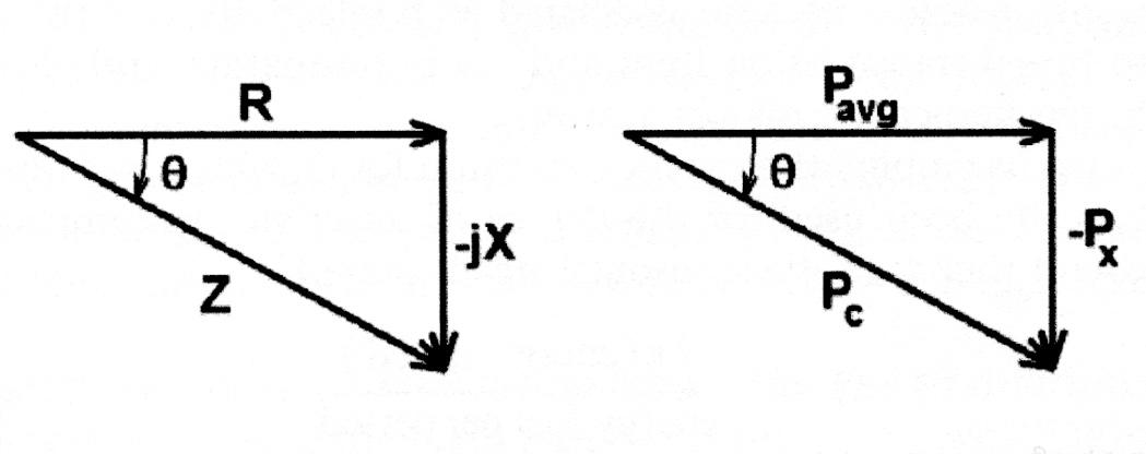
From the "power triangle" shown in Figure 2, it is easily seen that the power factor is the ratio of the average power (in watts) to the complex (or phasor) power (in Volt-Amperes),
$$ PF = \frac{P_r}{P_r \pm j P_x} = cos \; \theta = \frac{R}{\left| R \pm jX \right|} = \frac {1}{\left| 1 \pm jQ \right|} \rightarrow \frac{1}{Q} \; \; \; (31) $$
(Capacitive networks are said to have a leading power factor, and inductive networks have a lagging power factor.) When R << X, the power factor approaches 1/Q. Consequently, PF → 1/Q = R/|X| = 1/Γ. The more reactive the machine windings, the greater the phase angle θ and the lower the power factor. The greater the Goodness, the smaller the machine losses and smaller the (unloaded) power factor.
VII. Efficiency and Goodness
Efficiency is a measure of how well mechanical energy is converted into electrical energy. It may be defined simply as the magnitude of the quantity [1 - (ratio of the power loss to the input power)].32
(a) Derivation
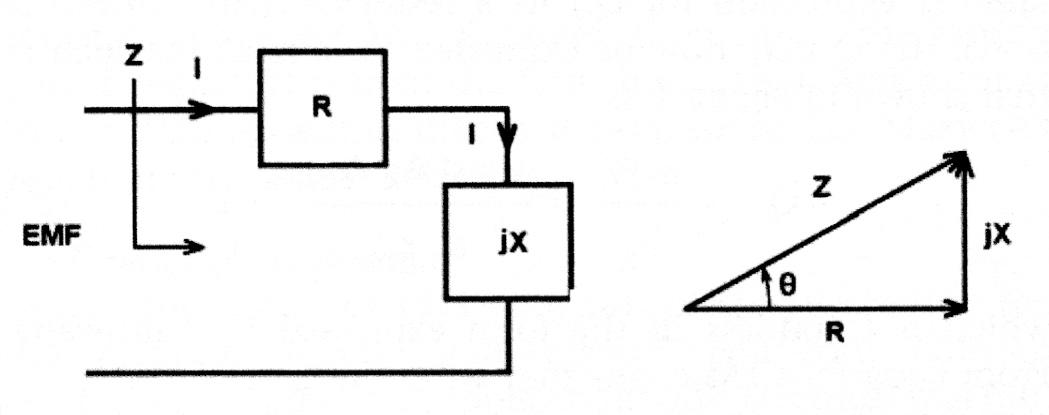
Consider the elementary generalized machine of Figure 1. Assume, for the sake of argument, that all the loss is confined to the electric circuit. The lumped element equivalent circuit can be thought to consist of an inductance in series with a resistance excited by an EMF.
Let jX be the inductive reactance (of the magnetic circuit associated with the B-field). If one regards the power dissipated in the resistive element (l2R) as the machine loss, then the efficiency may be expressed in terms of the Goodness as Equation 32:
$$ \eta = \left| 1 - \frac{P_R}{P_R + jp_X} \right| = \left| 1 - \frac{I^2R}{I^2R + jI^2 X} \right| \; \; \; (32) $$
or
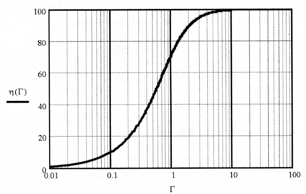
$$ \eta = \left| \frac{\Gamma}{\Gamma - j} \right| = \frac{\Gamma}{\sqrt{\Gamma^2 + 1}} \; \; \; (33) $$
This expression may be plotted as shown in Figure 4.
In Equation 33, Laithwaite's "Goodness," or ratio of free energy stored in the machine to work done against dissipation in the generalized circuit, is taken as
$$ \Gamma = \frac{X}{R} \; \; \; (34) $$
and this parameter is sufficient to specify the complete performance of all electrical and mechanical machinery.
This fundamental machine principle was recognized as early as 1930 by Gabriel Kron, when he wrote:
The criterion of good design of all electrical machines is expressed by a constant...which gives a measure of the effective utilization of iron and space for the transformation of energy. This constant plays a most fundamental role in the steady and transient behavior of machines...A relation of the form R/X is found for the ratio of the work done to the free energy and this one simple formula is sufficient to find the locus diagram and the complete performance of all electrical machines and transmission lines.33
The concept of Q was subsequently applied to RF transmission lines in 1934 by F.E. Terman,34 and then to cavity resonators in 1938 by W.W. Hansen.35
(b) Goodness Threshold: Γ = 1
We all recall that in order for second order differential equations of the form
$$ \frac{d^2 y}{dt^2} + \frac{\omega_o}{Q} \frac{dy}{dt} + \omega_o^2 \; y = 0 \; \; \; (35) $$
to have oscillatory modes as solutions, it is necessary that
$$ Q \; \geq \; \frac{1}{2} \; \; \; (36) $$
(This makes the roots of the spectral domain characteristic equation be complex.) It has been found that, in order for there to be sufficient torque for an electromagnetic motor to run, the Goodness of the machine has to be above a certain threshold value.36-38 This has been demonstrated for both rotary and linear AC induction machines. A classic historical example was the very first single-phase induction machine, which was invented by Tesla.
Laithwaite once wrote that Tesla's greatest achievement (the induction motor) is, "...even today, seldom associated with his name. Yet, over 90% of the total power of all electric drives in the world is vested in induction motors...Despite...the fact that every single-phase machine [Tesla] constructed failed to run...he went on pursuing the same goal relentlessly until, six years later, in 1888, he put some extra iron on the cross axis and found this to be the missing ingredient...In the case of the single-phase induction motor it is easily shown that unless the Goodness Γ is greater than one, the machine cannot run...[What] eluded Tesla for those six years...was that the Goodness of the magnetic circuit in the cross axis needed the attention rather than the more obvious main excitation axis."39
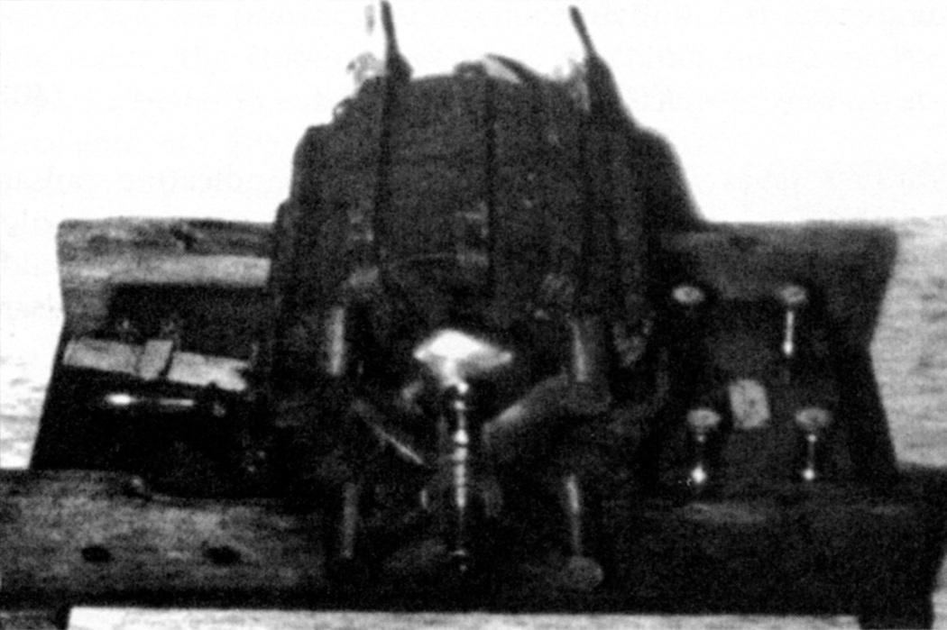
Incidentally, Tesla presented Professor Ayrton (who chaired one of the two February 1892 lectures that Tesla delivered in London) a small induction motor, which is still on display at the Science Museum near Imperial College in London. (See Figure 5. There is also a photo of this motor in the famous 1894 book by AIEE President T.C. Martin.40)
Goodness manifests itself wherever there is reactive energy stored and dissipation to be overcome. This occurs not only with rotating machinery, but also with mechanical oscillations and damping. A bouncing golf ball,41 for example, has a Q, or Goodness, of about 35. On the other hand, a spinning top with 80% of its mass concentrated in a rim whose thickness is less than 10% of its radius has a Goodness of only 6 or 8. Laithwaite applied his Goodness factor to the design of gyroscopes and found that gyros with the greatest Goodness have their mass concentrated in a thin rim linked by spokes of zero mass:
But the important point is that to display true gyroscopic phenomena it is necessary to have wheels with Γ values greater than 1 or it can never be made to run, as Tesla discovered for himself.42
There may be an implication here for vortex motion (smoke rings, whirlwinds, tornados, ball lightning models, and even toroidal GEONS43).
VIII. Les Grandes Spéculations
The concepts presented above all seem to point to Laithwaite's Goodness parameter as one of nature's universal criteria for characterizing fundamental phenomena. Mother Nature seems to be fond of certain notions and parameters. Surely, "Goodness" is manifested in celestial mechanics and cosmic electrodynamics!
Astronomical observations indicate that the rotation rate of the earth is decreasing (the length of the day is increasing: the moon is gaining energy and thus receding (it's a gravitational effect) at the rate of 0.00164 seconds per century. This would correspond to a terrestrial Goodness of Γ = 1.2 x 10¹².
A grand astrophysical example of Laithwaite's machine Goodness is exhibited by the Io-Jupiter dynamo. Io has a diameter of 3,640 km, a mass of 8.9x10²² kg, and orbits Jupiter at a distance of 421.6 Mm (only about 3 Jovian diameters; the equatorial radius of Jupiter is RJ = 71,398 km, and Jupiter's mass is MJ = 1.901x1027 kg), well within Jupiter's magnetosphere, with a period of 1.769 days. It has an atmosphere and at least seven active volcanoes, with plumes extending up to 250 km above the surface of the Jovian satellite. Io has an elliptical orbit, and it is so close that Jupiter's tug wrenches a moving tidal bulge on Io that heats it up, and this drives Io's volcanic activity - not some internal pressure or heat retained from the past.44 What a fantastic machine! (This is a literal illustration of Sir Hermann Bondi's famous Tweedledum-Tweedledee tale of Newtonian energy transfer by gravitation.45,46)
Apparently, due to the sputtering action of material ejected from Io and high energy particles bombarding this moon, a toroidal ring of charged plasma particles has been created around Jupiter at the radius of Io's orbit. The "plasma torus" is slightly inclined to the orbit of Io due to the presence of Jupiter's strong magnetic field. It has been hypothesized that the Io-Jupiter system forms an enormous electrical generator.47 The Jovian magnetic field at Io is about 1,900 nT and the motion of Io through Jupiter's magnetic field induces a v x B voltage across lo of about 400 kV.48 As a result, plasma electrons are driven along Jovian magnetic field lines forming a "flux tube" that connects Io and Jupiter's conducting ionosphere.
The current flowing between Jupiter and Io along this flux tube is in excess of 5 million amperes, and this gravitationally driven natural electrical generator has been estimated to develop a power level in excess of 1012 watts.49 (You can listen to radio noise generated by this system, at predictable times, with a shortwave radio tuned to about 21 MHz.50) One may ask himself, "What is the Goodness factor for this Jupiter-Io cosmic machine?" [Taking the moment of inertia as mR2, Γ ~ 1014.]

And, what about pulsars? The initial bar magnet models51 permit this intriguing description by John Kraus:
A pulsar is a super-dense neutron star with enormous magnetic (and gravitational field) that has a disc of magnetized plasma rotating with it as though frozen on. The edge of the disc may be traveling at the velocity of light with X-rays coming off from the rim, like sparks from a grinding wheel, as the rim interacts with the surrounding medium. The magnetic axis of the pulsar lies in the plane of the disc and is perpendicular to the rotation axis. The neutron star, or core of the pulsar, may be only about 10 km in diameter, while the disc may be several thousand km.52
Short pulses of radio energy are observed to emanate from such objects at a rate of about 30 per second (with an astonishingly constant pulse repetition rate) implying an angular velocity for the system of 30 revolutions per second (and a radius of R = c/ω = 1,600 km). Assuming the pulsar is about one solar mass (2x1030 kg), its rotational kinetic energy is given by
$$ K.E. \; = \; \frac{1}{2} I \; \omega_2 \; \; \; (37) $$
where, for a rotating bar magnet model,
$$ I \; = \; \frac{M\left(2R^2\right)}{12} = 1.04 \times 10^{38} \; kg \; m^2 \; \; \; (38) $$
with
$$ \omega = \frac{2 \pi}{1/30} = 188.5 \; rad/sec \; \; \; (39) $$
to give
$$ K.E. = 1.85 \times 10^{42} \; J \; \; \; (40) $$
Kraus gives RF power measurements indicating pulsar radiation at a rate of 5.62x10¹⁹ watts.53 Assuming the only energy lost by the pulsar is by radiation, Equation 27 would indicate a "Goodness factor" of Γ = 6.2x1024 for the pulsar model.
Well, what about galaxies? [The "Virial Theorem" is commonly used to gather information about star clusters and nebulae, but it assumes statistical equilibrium (no frictional loss) and that no "dark matter" is present.] The celestial mechanics is a little more challenging, but one can ask the question, "Which has the better ‘Goodness'?" - a spiral galaxy or an elliptical galaxy?" (Their age and matter distributions differ significantly.) Can "Goodness" be employed as a useful descriptor for galactic dynamics and for segregating and classifying galactic evolution? It would appear that the "Goodness" has degraded substantially in elliptical galaxies.
[For a cluster of stars to be held together as a stable system, the total kinetic energies of all of the stars must be equal to one-half of the (inverse-square) gravitational potential energies of all the stars added together. Otherwise, the cluster either collapses (insufficient KE) or the stars fly apart and escape (excessive KE). This is known as the Virial Theorem in classical and celestial mechanics.]
It has been argued that the Kerr metric (which exhibits angular momentum) describes the geometry of space-time external to a charged rotating black hole. Equation 26, at least within the event horizon, would seem to imply that rotating black holes, such as those appearing in galactic nuclei, are nature's ultimate electrical machinery - perverse as that might sound.
And so, we are back to ponder "Newton's bucket" (it has a Goodness factor, too) and Mach's Principle. The gyro space-drive controversy mentioned earlier notwithstanding, somehow one gets the impression that Laithwaite's intuition penetrated to cosmic machinery and one of the most universal properties of space-time itself.
IX. Hyper-Goodness
Before we close, we would like to put our engineering caps back on and go one step beyond, and tinker with the universe. What are the bounds placed upon us by Maxwell? Back in Section II we left that question unanswered. Laithwaite once said,
...there are definite limits to the extent to which the phenomena of electromagnetism can be exploited. Within these limits, however, there is much scope for inventive ingenuity, particularly as regards the shape of a machine.54
One can see this in his formula for Goodness. Clearly, if we "grease the bearings" and reduce friction, resistance and reluctance, the Goodness of these machines increases. We expect a better machine if we can build it out of zero-resistance wire, etc. But, we now ask ourselves, "For a given set of components, is it possible to beat the natural Goodness?"
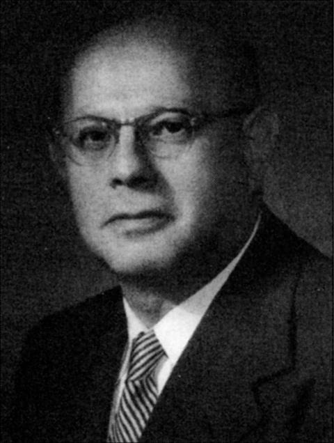
(a) Regenerative Radios
Edwin H. Armstrong (1890-1954)
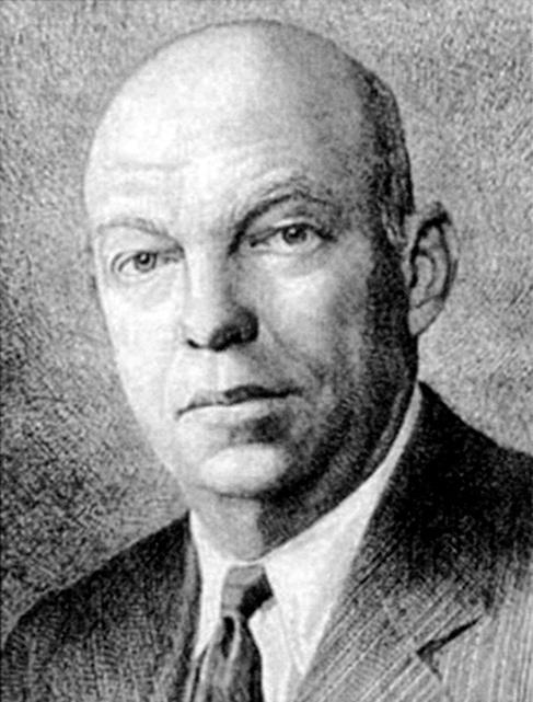
Up to this point, we have only considered "passive" Goodness. What happens if we inject negative resistance (or "negative reluctance") into these machines? The overall resistance would decrease and the goodness should rise.
The fundamental notion of electrical regeneration originated with Edwin Armstrong 55 - another genius of note. (H.A. Wheeler called Armstrong "the foremost inventor in the history of radio."56) Armstrong discovered the "Principle of Regeneration" at the age of 21, in 1912, and it has been called "probably the most significant discovery in the history of radio"57 and "one of the greatest factors in the advance of radio."58,59 Regeneration permits sensitivities right down to the noise floor. (For this Armstrong received the IRE's first Medal of Honor in 1917. He also received the Edison Medal, in 1942.) Many of Armstrong's inventions were claimed in patent lawsuits by men that were arguably greedy crooks, technical charlatans, and incompetent thieves. (Some even with academic credentials!) His tragic story is one of the most heart-rending legends in science.
Armstrong described the process in the following manner:
...the effect of regeneration (that is, the supplying of energy to a circuit to reinforce the oscillations existing therein) is equivalent to introducing a negative resistance reaction in the circuit, which neutralizes positive resistance reaction, and thereby reduces the effective resistance of the circuit.60
At the expense of an external power source, the regeneration process raises the effective Q, increases RF voltage magnification and enhances selectivity. Thirty years later Harris61 at MIT and Professor O.G. "Mike" Villard62 at Stanford took the notion one step further and developed the innovative Q-multiplier circuit for communication receiver selectivity.63,64 The process has even been performed with quantum systems at optical frequencies by employing a laser in one arm of a ring cavity for regenerative optical amplification.
(b) Parametric Regeneration
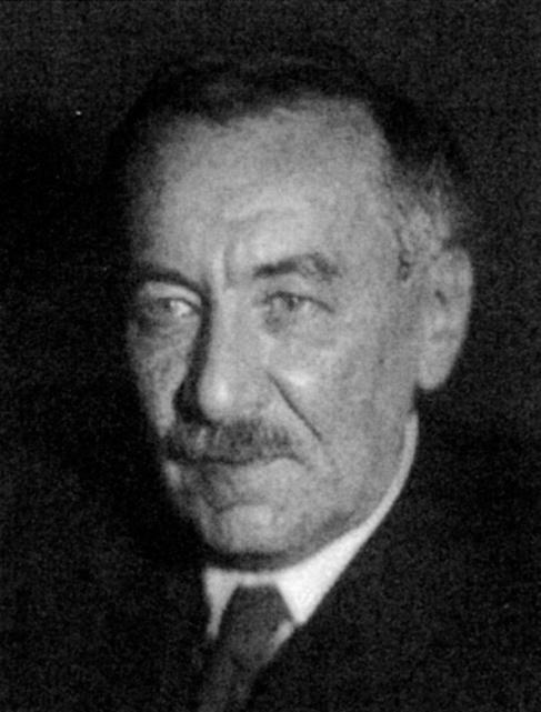
Regeneration can even be applied to mechanical oscillators, the most common of which are wheels and pendulums. A variant of the regenerative process was exploited by Physics Professor Leonid Mandelshtam and his students at Moscow State University during the early 1930s.
...by means of utilizing a local source it is possible to compensate for the losses of energy in a circuit performing forced oscillations if one of its [reactive] parameters is caused to vary at a suitable frequency.65
In classical regeneration, oscillation energy at the signal frequency (negative resistance) is increased at the expense of a power source (a battery). With parametric regeneration, the system contains some energy source together with a device for converting the energy of the source to replenish oscillations at some other frequency. This implies that energy at one frequency and a nonlinear or time-varying reactance is phased to create negative resistance (and, therefore, gain) at another frequency.66,67 Power flow in these nonlinear and time-varying systems is most easily characterized by the celebrated Manley-Rowe68,69 equations.
For the child on a swing, parametric regeneration (and the amplification of oscillations) is brought about by the child coherently raising and lowering the system's center-of-mass (the child "pumps") at a rate equal to twice the natural pendulum frequency of the system.70 Another famous example of growing oscillations by parametric regeneration (the length of the pendulum is pumped at 2ωo) is the swinging incense burner at the Shrine of St. James in Santiago de Campostella, Spain, and several enchanting videos of its growing oscillations appear on the internet.
[Incidentally, there is a threshold for parametric regeneration, too. Letting m be the relative variation in displacement about the mean center-of-mass, growing parametric oscillations will not commence unless the pumping causes m > 2/Q, or m > 2/Γ. The child on a swing figures out how to do this very quickly.]
We have observed RF regenerative negative resistance in the receivers of Nikola Tesla71 and have witnessed parametric negative resistance (at the difference frequency) in the Trichel pulse excited magnetic receiver of Mahlon Loomis (which apparently eluded the grasp of the "copycat" inventors of the magnetic detectors of the early twentieth century). The inherent regenerative gain from these processes results in remarkable sensitivity for these nineteenth century RF receivers [well under 100 uV RMS ("hard-microvolts") when measured by conventional receiver techniques72].
One of Mandelshtam's last students (V.V. Migulin) has described parametric regeneration as follows:
In an oscillatory circuit with a periodically changing reactive parameter at given frequency and phase relation, regeneration is described formally by an introduction of a negative resistance...In this case the energy is supplied into the system by the mechanism performing periodic changes in the reactive parameter. Such type of regeneration is called parametric regeneration...In addition to ordinary ohmic resistance, a negative resistance R- is inserted...Here lies the principle of operation of regenerative amplifiers of different types, parametric amplifiers among them.73
This leads us to ask what happens to Laithwaite's "Goodness" factor if any of the constitutive parameters are time varying. In particular, what happens to the Goodness of a motor if u is an appropriately varying function of time?
If the operating point on the B-H curve is displace and u is varied at a rate of, say, 2ωo will enough negative resistance be injected to raise the operating point "Goodness"? We think the answer is "Yes" and that Hyper-Goodness was actually demonstrated experimentally by Mandelshtam and Papalexi,74,75 and by their students.76 The latter citation, which varies L in Equation 17a at twice the oscillator frequency, clearly demonstrated the effect of negative resistance and a physical machine operating with parametric "Hyper-Goodness"! (The oscillation amplitude rose to the point of breakdown.) Unlike Tesla coils, which demonstrate voltage rise by means of wave interference on high VSWR, slow-wave, resonant, helical transmission lines77 (Tesla got past the lumped-element LC version in 1897), the 1930s electro-mechanical parametric machines of Mandelshtam are the AC counterparts to van de Graaff's DC generator.
In this regard, we call attention to the curious reactively tuned motors and generators among the patents of Nikola Tesla,78,79 and their possible operation in the "Hyper-Goodness" regime. We have much more to say about such a novel maneuver and will return to this intriguing topic at a later date.
X. A Final Observation
As a final note we wish to quote Laithwaite's comments on the effect of shape in different classes of machines. The "Goodness factor" derived above applies to electromagnetic machines. According to Laithwaite, these include synchronous, induction, and commutator motors. The Goodness expressions above do not embrace hysteresis machines, switched-reluctance motors, and permanent magnet motors. There is something different about them. These machines improve as they get smaller!
Laithwaite once wrote, "It has not yet been possible to unify magnetic machines in a single equation such as Eq. (4)."80
As mentioned above, we only used two of Maxwell's four equations (the curl equations). This paper is only a work-in-progress. There are yet two more Maxwell equations, and perhaps these provide the long-sought Goodness factor expression for magnetic machines.
With the approaching shortages of the rare earth elements neodymium and dysprosium for making high energy permanent magnets, this would give designers the tools they need for making very high efficiency and very high power-density motors and generators out of copper and iron for hybrid electric vehicles, wind turbine generators, and an assortment of renewable energy systems.
XI. Conclusions
This little discussion was merely intended to demonstrate that Kron's criterion of "good design" and Laithwaite's parallel concept of machine "Goodness" are contained within (and can be obtained directly from) Maxwell. Since Maxwell's equations are obtainable from an action principle, are metric independent,81 and obey the Principle of Electromagnetic Similitude (invariance under a change of scale),82,83 we conclude that "Goodness" is a fundamental property of the universe at large: like Q, the concept holds for systems characterized by an exchange of positive and negative reactive power, and even on a grand cosmological scale!
Further, by availing oneself of parametric pumping of either the geometry or the constitutive parameters it is possible to inject negative resistance into a system and exceed the natural limit on Q or Goodness obtainable with merely ergodic machines. (This is neither a violation of the Second Law of thermodynamics nor a "perpetuum mobile," of course, since energy is still conserved. Nor does it permit one to exceed the Chu Limit84,85 for electrically small antennas since the fundamental limitation there is radiation resistance not dissipative loss resistance.)
Professor Laithwaite's generalized machine is as fundamental as Maxwell, linking electrical and magnetic paths in space like Ezekiel's enchanting vision of fiery rings whose structure "...was as it were a Wheel in the middle of a Wheel."
Laithwaite not only opened our eyes (and minds!) to the optimization of "conventional" electrical machinery, but he has shown us the way to measure "Goodness" and how to use it as a tool of design, not merely analysis, as we dream new machines into existence. His technique is both theoretical and practical. And, he has cast light into the future.86
Many years ago mathematician Felix Klein (1849-1925) tried to find some analytical way to measure "Beauty." In his unsuccessful attempt at a geometrical criterion, Klein drew all parabolic lines on a photograph of the face of the statue of Apollo Belvedere.87 But, a criterion of "Beauty" eluded him. On the other hand, the notion of "Entropy" has had great utility. [Traditionally, entropy was utilized to characterize noise and measure "Disorder" in a system. And, until recently, entropy was used as the basis for distinguishing the "direction of time's arrow" (the phrase is Eddington's), which differentiates past from future. But, as Eddington has noted, entropy depends upon the collective qualities of a system as a whole, and not its parts.88]
It has been argued that "Beauty" is a function of configuration and therefore cannot be distilled and localized in space.89,90 From these examples, it would appear that "Goodness" (like Q, but unlike "Beauty") is a quantity that applies to lumped elements and spinning particles and, therefore, can be localized in space.
Richard Feynman once said, "Nature uses only the longest threads to weave her patterns, so that each small piece of her fabric reveals the organization of the entire tapestry."91 Surely, "Goodness" is one of those long, long threads.
Acknowledgments
For numerous historical and technical discussions the authors wish to thank James Hardesty of PV Scientific, Dr. Price Kagey of Surface Optics Corporation, and our former colleagues at the Institute for Scientific Research in Fairmont, West Virginia. Special thanks also go to Peter J. Pesavento for performing extensive Russian translations and commentary.
References
- Kron, G. 1930. "Generalized Theory of Electrical Machinery," AIEE Trans., 49, Pt. 1, 666-685.
- Laithwaite, E. 1975. "Linear Electric Machines: A Personal View," Proc. of the IEEE, 63, 250-290.
- Valone, T.F. 2002. "Eric Laithwaite Report: Gyromagnetic Engineering Genius; Publications, Inventions & News Clips," prepared for Bell Curve Research Foundation by Integrity Research Institute, December, Report # |R|PR-02-005.
- Thomas, N.T. and Millis, M.G. 2002. "NASA Breakthrough Propulsion Physics Project: Common Errors," October 21, http://www.asps.it/errors.htm
- Millis, M.G. and Thomas, N.T. 2006. "Responding to Mechanical Antigravity," 42nd Joint Propulsion Conference and Exhibit, AIAA, Sacramento, CA.
- Solomon, B.T. 2006. "Does the Laithwaite Gyroscopic Weight Loss Have Propulsion Potential," http://www.iseti.us/WhitePapers/ISDC2006/Solomon-ISDC-2006-05-07(LGWL).pdf
- Laithwaite, E.R. 1994. An Inventor in the Garden of Eden, Cambridge University Press, p. 54.
- Driga, M.D. 1997. "A Generalized Goodness Function and Quality Factors of Advanced Electrical Machines for Hypervelocity Accelerators," 11th IEEE International Pulsed Power Conference, Digest of Technical Papers, Baltimore, MD, Vol. 1, pp. 231-240.
- Giner, V., Sancho, M., and Martinez, G. 1995. "Electromagnetic Forces on Dissipative Dielectric Media," American Journal of Physics, 63, 749-753.
- Paris, D.T. and Hurd, F.K. 1969. Basic Electromagnet Theory, McGraw-Hill, p. 504.
- Corum, K.L. and Corum, J.F. 2001. "RF Coils, Helical Resonators and Voltage Magnification by Coherent Spatial Modes," Microwave Review, 7, 2, September, 36-45. Available online at: http://www.mwr.medianis.net/pdf/Vol7No2-07-JCorum.pdf
- Laithwaite, E.R. 1965. "The Goodness of a Machine," Electronics & Power, March, 101-103.
- Shakespeare, W. A Midsummer Night's Dream, Act V, Sc.l.
- Laithwaite, E.R. 1966. Propulsion Without Wheels, Hart Pub. Co., pp. 71-72.
- Steinmetz, C.P. 1900. "Alternating Current Phenomena," Electrical World and Engineer, p. 237.
- Laithwaite, E.R. 1965. "The Goodness of a Machine," Electronics & Power, March, 101-103.
- Ibid., pp. 101-103.
- Johnson, P.O. 1965. "Ball Lightning and Self-Containing Electromagnetic Fields," American Journal of Physics, 33, 119-123.
- Corum, K.L. and Corum, J.F. 1990. "High Voltage RF Ball Lightning Experiments and Electro-Chemical Fractal Clusters," Soviet Physics Uspekhi, 160, 4, April, 47-58 (published in Russian).
- Laithwaite, E.R. 1987. A History of Linear Electric Motors, Macmillan, p. 6.
- Laithwaite, E.R. 1965. "The Goodness of a Machine," Proc. IEE (London), 112, pp. 538-542.
- Laithwaite, E.R. 1966. Propulsion Without Wheels, The English Universities Press, pp. 71-78.
- Laithwaite, E.R. 1971. Linear Electric Motors, Mills & Boon Limited, p. 37.
- Spurgeon, C.H. "The Chariots of Ammi-Nadib."
- Schmid, A. 1891. "Electrical Engineers: Alfred Schmid," The Electrical Engineer, 11, p. 623.
- Harrington, R.F. 1960. Time Harmonic Fields, McGraw-Hill, pp. 19, 23.
- Ibid., pp. 31-32.
- Corum, K.L., Pesavento, P.V., and Corum, J.F. 2006. "Multiple Resonances in RF Coils and the Failure of Lumped Inductance Models," Proc. Sixth International Tesla Symposium, October, Belgrade, Serbia, http://www.nedyn.com/TeslaIntlSymp2006.pdf
- Green, E.I. 1955. "The Story of Q" American Scientist, 43, 584-595.
- Johnson, W.C. 1950. Transmission Lines and Networks, McGraw-Hill, p. 172-175.
- Laithwaite, E.R. 1987. A History of Linear Electric Motors, Macmillan, p. 6.
- Fitzgerald, A.E. and Kingsley, C. 1961. Electric Machinery, McGraw-Hill, p. 345.
- Kron, G. 1930. "Generalized Theory of Electrical Machinery," AIEE Trans., 49, Pt. 1, 666-685.
- Terman, F.E. 1934. "Resonant Lines in Radio Circuits," Electrical Engineering, July, 1046-1053.
- Hansen, W.W. 1938. "A Type of Electrical Oscillator," Journal of Applied Physics, 9, October, 654-663.
- Laithwaite, E.R. 1965. "The Goodness of a Machine," Proc. IEE (London), 112, pp. 538-542. (See p. 540.)
- Laithwaite, E.R. 1965. "The Goodness of a Machine," Electronics & Power, March, 101-103.
- Laithwaite, E.R. 1966. Propulsion Without Wheels, The English Universities Press, pp. 94-97.
- Laithwaite, E.R. 1990. "The Inventions of Nikola Tesla," Tesla Journal, pp. 88-95.
- Martin, T.C. 1894/1992. Inventions, Researches and Writings of Nikola Tesla, The Electrical Engineer, republished by Barnes and Noble, p. 481.
- Hayt, W.H. and Kemmerly, J.E. 1978. Engineering Circuit Analysis, McGraw-Hill, 3rd edition, p. 450.
- Laithwaite, E.R. 1990. "The Inventions of Nikola Tesla," Tesla Journal, 88-95.
- Wheeler, J.A. 1955. "GEONS," Physical Review, 97, 511-536.
- Miller, J. 2009. "Analysis Quantifies Effects of Tides in Jupiter and Io," Physics Today, August, 11-12.
- Bondi, H. and McCrea, W.H. 1960. "Energy Transfer by Gravitation in Newtonian Theory," Proc. Cambridge Phil. Soc., 556, pp. 410-413.
- Bondi, H. 1965. "Some Special Solutions of the Einstein Field Equations," in Lectures on General Relativity: 1964 Brandise Summer Institute in Theoretical Physics, Vol. 1, edited by A. Tautman, F.A.E. Pirani and H. Bondi, Prentice-Hall, pp. 375-459. See pp. 431-434.
- Goldreich, P. and Lyndon-Bell, D. 1969. "Io: A Jovian Unipolar Inductor," Astrophysical Journal, 156, p. 59.
- Smoluchowski, R. 1975. "Jupiter 1975," American Scientist, 63, 638-648.
- Corum, K.L. and Corum, J.F. "Tesla and the Signals of Planetary Origin," internet version at Tesla Mem. Soc. of New York: http://www.teslasociety.com/mars.html
- Flagg, R. See: http://www.radiosky.com
- Rees, M.J. 1971. "New Interpretation of Extragalactic Radio Sources," Nature, January 29, 229, 312-317.
- Kraus, J.D. 1980. Our Cosmic Universe, Cygnus-Quasar Books, p. 189.
- Kraus, J.D. and Carver, K.R. 1973. Electromagnetics, McGraw-Hill, pp. 702-704, 715, 811.
- Laithwaite, E. 1975. "Linear Electric Machines: A Personal View," Proc. of the IEEE, Vol. 63, pp. 250-290.
- Armstrong, E.H. 1917. "A Study of Heterodyne Amplification by Electron Relay," Proc. IRE, Vol. 5, pp. 146-148.
- Wheeler, H.A. 1948. "A Simple Theory and Design Formulas for Superregenerative Receivers," Wheeler Monographs, 1, 3, pp. 1-46.
- Kitchin, C. 1994. "Super-Regeneration," Communications Quarterly, Fall, pp. 27-40.
- Landon, V.D. and Jarvis, K.W. 1925. "An Analysis of Regenerative Amplification," Proc. IRE, 13, 6, December, pp. 707-753.
- Cotanis, N. 1997. "The Radio Receiver Saga: An Introduction to the Classic Paper by Edwin Armstrong," Proc. IEEE, Vol. 85, pp. 681-684.
- Armstrong, E.H. 1922. "Recent Developments of Regenerative Circuits," Proc. IRE, Vol. 10, pp. 244-260.
- Harris, H.E. 1951. "Simplified Q Multiplier," Electronics, May, pp. 130-134.
- Villard, O.G. and Rorden, W.L. 1952. "Flexible Selectivity for Communications Receivers," Electronics, April, pp. 138-140.
- McCoy, L. 1956. "The Heathkit Q Multiplier," QST, April, p. 39.
- Cohen, S. 2006. "The Collins 75A-4 Receiver," QST, January, pp. 36-39.
- Mandelshtam, L.I., Papalexi, N., Andronov, A., Chaikin, S., and Witt, A. 1935. "Report on Recent Research on Nonlinear Oscillations," Tech. Phys. of the USSR, Leningrad, 2, 2-3, pp. 81-134, http://www.nedyn.com/Mandelstam.html.
- Manley, J.M. and Peterson, E. 1946. "Negative Resistance Effects in Saturable Reactor Circuits," AIEE Transactions, 65, December, pp. 870-881.
- Manley, J.M. 1960. "Some Properties of Time-Varying Networks," IRE Transactions on Circuit Theory, 7, 5, August, pp. 69-78.
- Manley, J.M. and Rowe, H.E. 1956. "Some General Properties of Nonlinear Elements, Part I: General Energy Relations," Proc. IRE, 44, pp. 904-913.
- Rowe, H.E. 1958. "Some General Properties of Nonlinear Elements, Part II: Small Signal Theory," Proc. IRE, 46, pp. 850-860.
- Cunningham, W.J. 1958. Introduction to Nonlinear Analysis, McGraw-Hill, p. 276.
- Corum, K.L. and Corum, J.E "Tesla's Colorado Springs Receivers," Tesla Memorial Society of New York: http://www.teslasociety.com/teslarec.pdf
- Pappenfus, E.W., Bruene, W.B., and Schoenike, E.O. 1964. Single Sideband Principles and Circuits, McGraw-Hill, pp. 340-343.
- Migulin, V.V., Medvedev, V.I., Mustel, E.R., and Parygin, V.N. 1983. Basic Theory of Oscillators, Mir Publishers, pp. 142-143.
- Mandelshtam, L.I., Papalexi, N., Andronov, A., Chaikin, S., and Witt, A. 1935. "Report on Recent Research on Nonlinear Oscillations," Tech. Phys. of the USSR, Leningrad, 2, 2-3, pp. 81-134, http://www.nedyn.com/Mandelstam.html. See pp. 122-128.
- Mandelshtam, L.I. and Papalexi, N. 1933. "Oscillations in an Electrical System Energized By Means of Periodically Changing Capacities," Zhurnal Tekhnicheskoi Fiziki, 3, 7, pp. 1141-1144. (Translated by P.J. Pesavento, http://www.nedyn.com/para.html - Item #1.)
- Lazarev, V.A. 1934. "On Hetero-Parametric Excitation," Zhurnal Teknicheskoi Fiziki, 3, pp. 30-4.7 (Translated by P.J. Pesavento, http://nedyn.com/translations.html.)
- Corum, K.L. and Corum, J.F. 2001. "RF Coils, Helical Resonators and Voltage Magnification by Coherent Spatial Modes," Microwave Review, 7, 2, September, pp. 36-45, http://www.mwr.medianis.net/pdf/Vol7No2-07-JCorum.pdf.
- Tesla, N. "Electric Generator," U.S. Patent #511,916 (Filed: August 19, 1893; Issued: January 2, 1894).
- Tesla, N. 1992. Nikola Tesla on His Work with Alternating Currents and Their Application to Wireless Telegraphy, Telephoney and Transmission of Power, edited by L.I. Anderson, Sun Publishing, pp. 38-39.
- Laithwaite, E.R. 1971. Linear Electric Motors, Mills & Boon Ltd., p. 39.
- van Dantzig, D. 1934. "The Fundamental Equations of Electromagnetism, Independent of Metrical Geometry," Proc. Cambridge Phil. Soc., 30, pp. 421-427.
- Stratton, J.A. 1941. Electromagnetic Theory, McGraw-Hill, pp. 488-490.
- Paris, D.T. and Hurd, F.K. 1969. Basic Electromagnetic Theory, McGraw-Hill, p. 508.
- Chu, L.J. 1948. "Physical Limitations of Omnidirectional Antennas," J. Appl. Phys., 19, pp. 1163-1165.
- Wheeler, H.A. 1947. "Fundamental Limitations of Small Antennas," Proc. IRE, 35, December, pp. 1479-1488.
- Laithwaite, E.R. 1991. "The Way Ahead," IEEE Transactions on Magnetics, 27, pp. 7-10.
- Goetz, A. 1968. Introduction to Differential Geometry, Addison-Wesley, pp. 172-173.
- Eddington, A.S. 1929. The Nature of the Physical World, Macmillan, p. 103.
- Mason, M. and Weaver, W. 1929. The Electromagnetic Field, University of Chicago Press, pp. 266-267.
- Stratton, J.A. 1941. Electromagnetic Theory, McGraw-Hill, p. 110.
- Feynman, R. 1965. The Character of Physical Law, MIT Press, p. 34.
About the Authors
Dr. James F. Corum holds the following degrees: BSEE (Lowell Tech. Inst., 1965), MSEE (Ohio State, 1967), and Ph.D. in Electrical Engineering (The Ohio State University, 1974). Corum began his professional career as an electronic engineer at the National Security Agency. Subsequently, he taught at several academic institutions and conducted research in electronics (antennas and RF), physics (radio astronomy, electrodynamics, general relativity), and mathematics (differential geometry and non-Riemannian manifolds). He was an Associate Professor of Electrical Engineering at West Virginia University, a Professor of Physics and Applied Mathematics at Ohio Institute of Technology, and a Senior Research Scientist at the Battelle Institute (Columbus, Ohio). He was Chief Scientist for Science Applications Research Associates (Huntington Beach, California) and Chief Scientist for the Institute for Scientific Research (Fairmont, West Virginia). He presently serves as President and Chief Technical Officer for National Electrodynamics. Corum has published over 100 technical papers and several monographs. He is the inventor of the contra-wound toroidal helix antenna and holds five patented RF inventions (with six more patents pending on the power grid Ring Power Multiplier device).
Kenneth L. Corum holds a B.A. in Physics from Gordon College (1976) and attended graduate school in Electrical Engineering at the University of Massachusetts. Corum taught high school physics and general science in Massachusetts. He then entered private industry and taught computer electronics, digital techniques, and software engineering for Compugraphic Corporation, ATEX/Kodak, and Sun Microsystems in England, France, Germany, Switzerland, the Netherlands, Russia, and across the U.S. He was also employed by the Microwave Semiconductor Division of Varian Associates (Beverly, Massachusetts) where he developed Schottky diodes, IMPATT oscillators, and other microwave RF semiconductor devices. Corum was Director of the Commercial Satellite Division of Pinzone Communications (Cleveland, Ohio). He was a software consultant with Hewlett-Packard, and is currently staff consultant for Sun Microsystems (Burlington, Massachusetts). Corum is the discoverer of the modulated common-mode RF-backscatter phenomenon from baseband differential-mode nonlinear targets. He has co-authored six technical books and published more than 60 papers (mostly on antennas and RF technology) and dozens of training manuals for the short courses which he has taught over the years.
Philip V. Pesavento holds a BSEE from Carnegie Institute of Technology (now Carnegie-Mellon University, 1980); Advanced Technical Education Program (ATEP) Hughes Aircraft Company, 1980-1987; Advanced Studies (University of Southern California, 1985; and UCLA, 1996). Pesavento worked from 1980 to 1987 for the Hughes Aircraft Company as part of the Radar System Group in the Advanced Manufacturing Technology Development Laboratory (El Segundo, California). He has also been employed at: Microwave Acoustics Laboratory of the Space and Communications Group at TRW (Redondo Beach, California, 1987-1988); Henry Radio (Los Angeles, California, 1988-1995) in the high power RF transmitter division; Scientific Applications and Research Associates (Huntington Beach, California, 1995-2000) where he worked on high power acoustics and high velocity ring vortex generators, etc.; Institute for Scientific Research (Fairmont, West Virginia, 2000-2005) as a principal member of the research staff on electric propulsion space-drives, high power resonant ring technology, and RF systems; and Powercast Corporation (Pittsburgh, Pennsylvania, 2007-2008) working on wireless energy harvesting. He has served as a senior consultant since 2005 for National Electrodynamics (Morgantown, West Virginia), where he has developed nonlinear and time-varying systems and sensors, and for Texzon Utilities (Dallas, Texas) where he has developed 60 Hz ring power-multipliers for power grid applications. Pesavento has published a dozen technical papers and authored 35 technical reports. He holds four U.S. patents (Photoconductive Power Switches; System For Sensing Ions In Aqueous Solutions; Method For Connecting Leadless Chip Package; and Carbon-Air Fuel Cell), and currently has several foreign and domestic patents pending on power grid applications.
*Email: [email protected]
**Email: [email protected]
***Email: [email protected]