Nikola Tesla Articles
Nikola Tesla's Power Oscillator Concept and Energy Resonance
Shortcomings of DC Power
The limitations of our present power generation and transmission systems are becoming more and more evident as time goes on. This is ironic considering the fact that the original inventor of the polyphase electric system warned of its eventual shortcomings nearly one hundred years ago. During the early 1900's, Nikola Tesla made announcements concerning the limitations of his alternating current system, and the development of a novel means of electrical power transmission that could service the energy needs of the entire globe without wires. So fantastic were these new claims, and so far beyond the abilities of his engineering peers, that they were harshly ridiculed and rapidly dismissed by the scientific community. But, was there any validity to Tesla's claims?
The historical development of electrical physics has proceeded along a very definite evolutionary course, and is quite easy to follow. Every schoolchild knows that the science of electricity was first commercialized in the United States by Thomas A. Edison. Edison utilized the technology of his day, Direct Current, to construct his electrical energy empire. However, DC has several inherent drawbacks. It must be transmitted at the potential at which it is generated; it cannot be transformed to higher voltages. Consequently, customers near the generation facility received too much voltage, while those at the far end of the line enjoyed a perpetual brownout.
DC motors of the day were huge inefficient monsters, which required noisy, sparking commutators. Not only were these machines large and expensive, but they had to be timed in accordance with their load requirements and maintained constantly. Yet, the Edison System was considered the wonder of his day.
AC Power
Tesla invented the Alternating Current motor in 1888, and changed the entire electrical landscape almost overnight. His AC power transmission system could make use of distribution transformers to ensure an even allotment of potential to all customers. AC motors turned without commutators and were closely synchronized to one another by means of the line frequency. All and all, the entire polyphase innovation was much more efficient and considerably less expensive. Turn of the century engineers honestly believed that the zenith of electrical engineering had been reached. How could Tesla's AC system possibly be improved upon? The answer is quite surprising, but requires a bit explanation before it can be readily understood.
The nature of AC Power requires the simultaneous utilization of an alternating current and an alternating potential. Where resistive loads are concerned, these components are exactly in phase with one another. Hence, the resulting power, which is the product of the two waves, can be mathematically represented by a "sine squared" wave. Such a wave undulates, but it does not alternate. This means that the wave function has no negative going aspect. The function literally sits upon the positive X axis when geometrically represented.
In essence, this means that despite the complexity of the wave involved, AC Power has a positive average value which can be represented by a simple straight line. Strangely, DC Power is mathematically identical to AC Power in this respect.
Functionally, AC can be viewed as a more sophisticated version of DC, with several very attractive attributes that make it far superior to common DC from the standpoint of transmission efficiency and overall versatility. Shortly after the turn of the twentieth century, Tesla was experimenting with one wire transmission systems and completely wireless power transmission systems. Both of these striking innovations utilized a new form of power unlike DC or AC. This novel electrical agency was known to Tesla as Oscillated Power, or OP.
Oscillated Power
Oscillated Power is actually true AC Power, for in addition to the alternating current, and the alternating voltage, OP also develops an alternating power wave, power that contains a negative going component. This negative component signifies a reversal of direction or flow. Whereas standard power moves only from source to load, Oscillating Power also flows from load to source. In an OP system with 100% reflection efficiency, the net power consumption would always be zero! This is a concept that is somewhat difficult to comprehend. Perhaps a good analogy will promote a rapid understanding.
Functionally speaking, any power grid can be likened to a large storage tank filled with a non-compressible fluid. Accordingly, the generators supplying the grid can be compared to huge pumps which are lifting the fluid up into the tank, and supplying the operating pressure. When a switch is closed connecting the grid to a load, it is like opening a valve which allows our operating fluid to escape into a particular appliance or load with as much "flow" as the connecting plumbing will bear at the applied pressure.
Once the operating fluid has passed through the appliance in question, its "Potential Energy" is spent, and fluid is simply returned to the pumping station (Generator) so it can again be "worked upon" and it's potential renewed. Thus, the grid is kept "pressurized" by the action of the generators. However, this process requires the constant consumption of fuel in proportion to the work being done. Hence, the system which we now utilize can never see any "gains" or hyper-efficiencies, simply because it is totally linear in design and function. However, consider the following variation in the scheme.
The same grid is again pressurized by its generators. However, the remainder of the activity is totally different. When a switch is closed in the Oscillating Power System, the working fluid flows through the connective plumbing as before, but, it passes through the appliance in question, and then enters a large spring loaded piston. The line pressure causes this piston to expand, thus compressing the spring and storing energy again as potential: At the appropriate moment in time, the spring is allowed to return to its original length, driving the working fluid back through the appliance and back upon the grid. Thus, the operating pressure is renewed without additional assistance from the generators. Accordingly, the unused energy is returned to the grid, "free of charge", for future use. This process is made possible only because of the change in direction of the Power flow.
Initially power moves from the grid to the load, then from the load back to the grid. No other power system that I know of operates in this manner. I hope that this illustration has provided a better shade of understanding for the reader. Please bear in mind, however, that it should not be taken literally. The actual process involved is considerably more complex than my example, and completely nonlinear in nature. The Power Oscillation process is based upon the laws of Energy Resonance, a phenomenon that will now require an explanation.
Energy Resonance
The concept of Energy Resonance is a difficult idea to portray. The reasons for this seem to be twofold:
- Most people have very poor notions about the physical laws regarding Energy, Work and Power. Unlike force, which is very intuitive, these other parameters can only be appreciated through an acquired sense of "feel" which must be developed through many years of thought, experimentation and calculation.
- Energy Resonance is further complicated by the fact that it is intrinsically associated with "form;" form that changes dynamically in space, in time, or in both, and as such, is demonstrated only within nonlinear systems.
In essence, Energy Resonance is a kind of system optimization similar in nature to Frequency Resonance, but far more complex. Frequency Resonance is usually associated with electrical circuits, although the concept is also valid in mechanics, optics and a myriad of other fields. When utilized electrically, the phenomena is often associated with tuning, for example, channel selection.
Imagine the great influx of radio waves that impinge on an antenna. There are AM stations, FM stations and numerous sources of "radio frequency noise." If your intention is to tune into WOR, for instance, the receiving circuitry must be able to discriminate between that station and all the other "information" surging about at different frequencies.
The required tuning action is provided by a "tank circuit" or resonant filter, which is composed of an inductor and a capacitor connected in series. Usually the capacitor is adjustable in its electrical value. The properties of a tank circuit are such that the current flowing through it "peaks" to a maximum value for a specific frequency when the inductance and the capacitance have very specific electrical values. The intensity of the current at resonance can be hundreds, even thousands of times greater than it is off resonance. Hence, it is possible by this mechanism, to have dozens of currents flowing in a radio's detection circuit, while optimizing or selecting one particular frequency for amplification and listening.
Unlike Frequency Resonance, which is an optimizing of an electric current at a specific frequency, Energy Resonance is the optimizing of electrical energy within various types of circuits such that a minimum amount of power is required to operate those circuits. This can best be understood by studying an example taken from classical mechanics.
Consider what happens if a stone is dropped from a very high building. Under the influence of gravity, it will immediately begin to accelerate and to acquire Kinetic Energy. The movement of the stone will be in accordance with the law:
!$ {S = {1 \over 2} gt^{2}} !$
This simply means that the displacement (S) of the object through the air (neglecting friction) will be proportional to one half the acceleration of gravity (g) times the passage of time (t) squared. Hence, it becomes obvious that the stone "falls" through greater and greater segments of the earth's gravitational potential in each second of time. Accordingly, it will acquire energy from the environment as a square law function. Example, 1, 4, 9, 16, 25, 36 Joules, etc.
The power propelling the stone can best be described as the time derivative or rate of change of the Kinetic Energy. The derivative of a square law function is always a linear function, such that the power increases as 1, 2, 3, 4, 5, 6 Joules/sec, etc. this indicates that the "system" utilized in this example has not been optimized, for both the Kinetic Energy and the required Power are increasing as a function of time, although at different rates. From the Energy Resonance point of view, the falling stone is severely overdriven; it is absorbing more energy than necessary to accomplish its descent.
However, suppose that an "impedance" is imposed which alters the stones path of decent from a vertical straight line, to that of a particular curve. This impedance must be "structured" in space, such that the acquired Energy of the stone moving along its surface will become "structured" in time. Both parameters will, thereby, acquire "form." Please note that structuring the profile of the accrued energy in time does not violate any physical law. Energy is always conserved, and this holds absolutely true in Energy Resonant systems as well as in any other. However, if the energy profile of the falling object is adjusted in time so that it approximates a linear function, something absolutely remarkable occurs.
Please note, that if the Energy is forced to accrue linearly with respect to the passage of time (1, 2, 3, 4, 5, 6 Joules, etc.). Then the time rate of change of this energy function is again the Power required. However, the rate of change of a linear function with respect to time is always a constant! Hence, as the "linearized" Energy increases, the necessary Power does not! This is an astounding observation and it clearly demonstrates the superiority of Energy Resonant Technology with respect to standard energy economics.
Mathematical analysis of the descending stone in the second case, actually demonstrates that there is a work advantage in allowing the falling object to follow the curved path, but miraculously, Energy is still conserved! This is possible because of the mathematics of calculus and the manner in which complex derivatives are taken. However, from a practical point of view, it means that circuits can be designed and constructed which operate in accordance with these new laws and thereby secure the same "work advantage." Such is the case with all Power Oscillating Systems, but, they need not be electronic circuits.
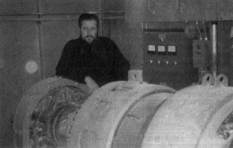
The original work done in this field by the author, was embodied in electromechanical machinery. In fact, the inspiration for studying Energy Resonance came from experiments performed with an 800 KVAR Synchronous Capacitor, which I constructed for Bethlehem Steel Corporation during the 1970's, (See Photo #1).
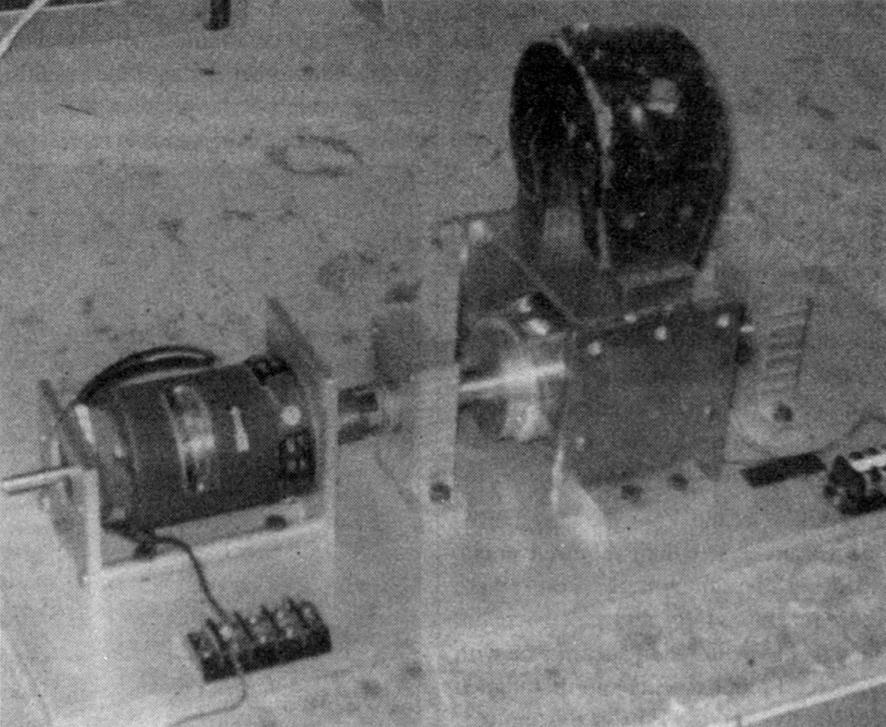
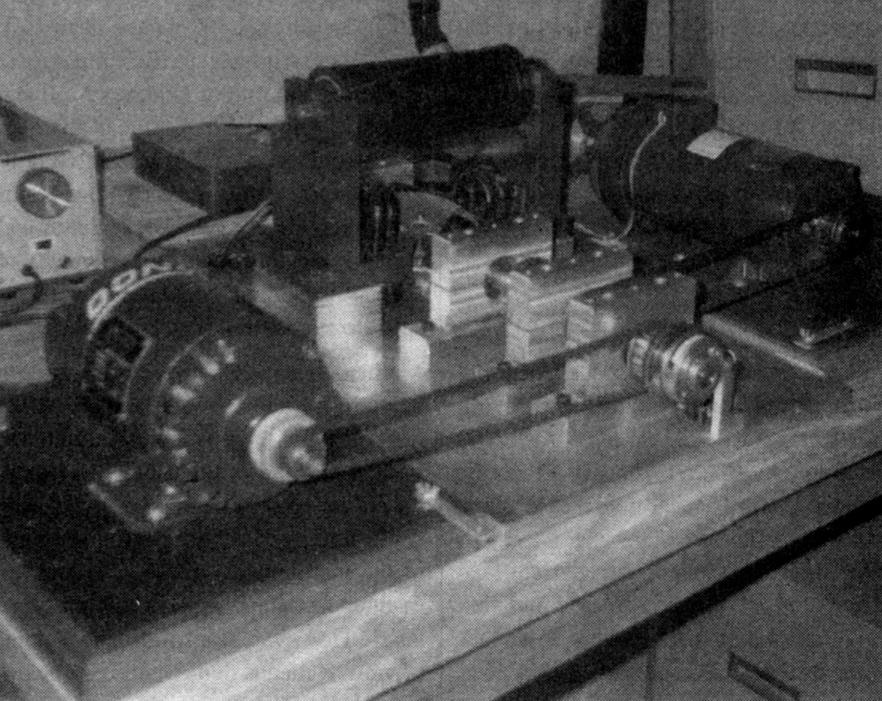
Subsequent developments in operational theory and physical design eventually gave rise to the Dynaflux Alternator, which received a patent in 1988, (See Photo's 2 & 3).
The perpetual state overload upon our transmission grids, and the rising costs associated with the generation and transmission of electrical power would seem to indicate very strongly, that the time has come for innovation and change within the Utility Industry. Might it not be prudent to re-examine the solutions proposed by the genius who invented the entire system in the first place? Or shall we elect to ignore his suggestions, and propel ourselves into a new dark age sometime during the 21st Century? __JM
