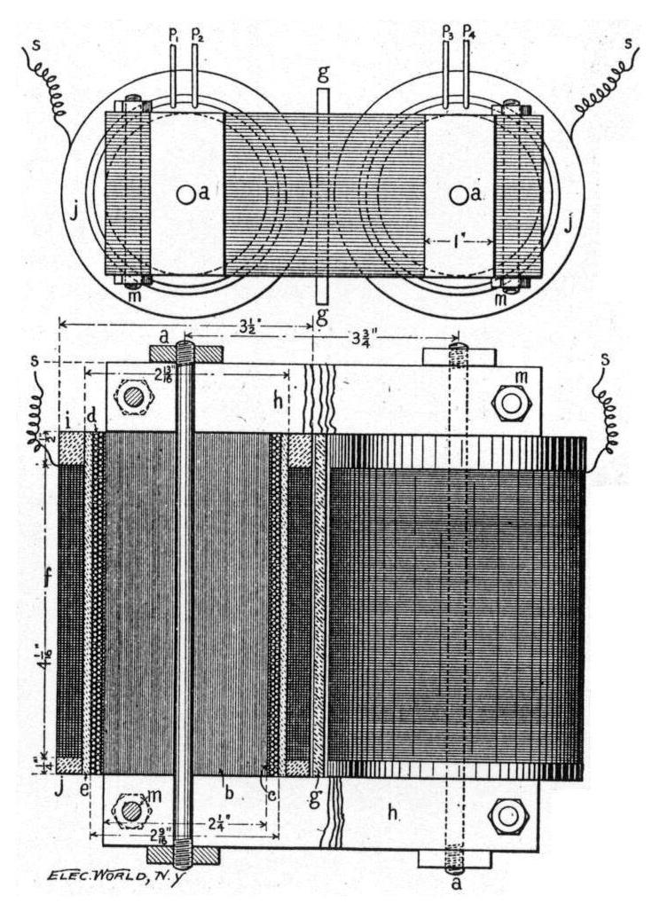
The chief and almost the sole difficulty encountered in the construction of efficient oscillatory current apparatus of reasonable size is in obtaining sufficient and permanent insulation. The liking of a high-potential high-frequency current for any path of discharge beside that between the terminals will often drive the experimenter to despair. A few general facts therefore in regard to the subject of insulators and insulation will not be out of place.
Fig. 11.
As Professor Fessenden has pointed out in a recent paper read before the American Institute of Electrical Engineers and printed in THE ELECTRICAL WORLD, April 2, 1898, we may speak of an insulating substance as that which will more or less effectually prevent a slow leakage of the electric current or as a substance which, permitting more or less leakage, will prevent a disruptive or sudden discharge. These two aspects of an insulator may be very prettily illustrated as follows: Provide a glass tube about an inch in diameter with a tight fitting cork for each end. Insert a pointed wire through each cork, so that the two wires will come within the tube and be capable of meeting at its centre. Fill the tube with ordinary water and pull the two ends of the wire a short distance apart. If a high-frequency high-potential current source be attached to the ends of the wires outside the tube, it will be found that the water has considerable insulating power against a disruptive discharge. When the ends of the wires are sufficiently near, however, the discharge will pass through the water, giving a beautiful light. It will be observed, also, that bubbles come off everywhere from the sides of the wire. These show that considerable current is flowing through the water in the ordinary way, while the water is behaving as a highly insulating substance to the disruptive discharge. After the water becomes thoroughly fouled no disruptive discharge can be obtained, the current all passing through the water by electrolysis. The kind of insulation required for oscillatory currents is that which will prevent the disruptive discharge. For reasons to be shown an insulator may have enormous strength for an E. M. F. which acts for only an instant and yet be very weak for the same E. M. F. applied for a considerable time.
Fig. 12.
An experiment first performed by Faraday will teach us much about insulators. The experiment is illustrated in Fig. 11. p p are two circular brass plates with small holes h h in their centre. t is a tube with glass ends g g. Such a tube Faraday filled with carbon bisulphide and a great many short pieces of silk thread. By applying the eye to one of the holes h h he could not see through the tube because the short pieces of silk were turned in all directions. When, however, p p were given opposite charges of electricity the threads all arranged themselves in line and he obtained clear vision through the tube lengthwise. This shows that the silk is a better conductor of the lines of electric stress than the liquid in the tube. Now assume the silk to be also a poorer insulator than the liquid, and that the difference of potential of the two plates is so great that a discharge is just on the point of taking place between the plates through the liquid alone. At the first instant that the plates are charged the particles, supposedly of weak insulating power, will not be lined up, but after a greater or less time they will become so, when the path for the current to pass through being weakened by this alignment of the particles the discharge will occur. Thus we have one case in which an instantaneously applied E. M. F. would not break down an insulator, while one longer applied of the same value would. The same will hold true in a like measure if the two plates are being alternately charged with electricity of opposite signs. Now there are few oils or other insulating liquids which are perfectly pure and free from foreign particles, and the very effect here described often takes place, especially with high-potential currents of a moderate frequency. I have found oil, which had an instantaneous insulating value for the current from a high-potential transformer several times stronger than air, prove actually weaker than air for a long applied electric pressure. By making the insulator a solid we ought to prevent this polarization of the particles, but, with high-frequency currents, we fall in two other difficulties which are harder still to eliminate.
Almost all solids become conducting when hot, glass, for example, being an excellent conductor when melted.
Fig. 13.
A = plan, B = section of elevation.
a a = bolts, b b = iron cores of No. 16 soft annealed wire.
c c = paper insulation 1/32 of an inch thick.
d d = space for primary winding. This consists of 115 turns on each half of transformer, of No. 15 magnet wire wound in two layers.
e e = micanite tubes 1/8 of an inch thick to insulate secondary windings from primary.
f f = space for secondary windings which are wound in 26 sections for each side, 52 sections in all. Sections 3/32 of an inch thick, 1/16 of an inch of fiber insulation between each section. Depth of secondary winding may be increased if greater E. M. F. is required. Use double silk-covered No. 32 wire.
g = glass plate to prevent a discharge between the two halves of the transformer.
h h = iron yokes to complete magnetic circuit. These yokes should be built up of iron strips one inch wide and not over 1/16 of an inch thick and bolted together with bolts m m.
i i = red fibre or micanite rings.
j j = red fibre or micanite rings.
p₁ p₂ p₃ p₄ = ends of primary windings, which may be connected in series or multiple.
s s = ends of secondary winding.
Now it is a well-known fact that a high-potential high-frequency current will eat its way through the best of solid insulators a distance that it could not begin to penetrate at once, and that, too, when no air is present, the terminals being perfectly imbedded in the solid insulator. My own conception (formed probably by reading Professor Fessenden’s article on insulators) of one cause of this will be made plain by referring to Fig. 12. Let P and P′ be two metal plates of indefinite area. Suppose black fibre to be an insulating material between these plates and suppose this to be impure, having particles of some better insulating substance, but of higher specific inductive capacity than the fibre imbedded in it. Let p, m and n be three such particles. If P is charged positive and P′ negative the lines of electric stress, finding an easier passage through these particles, will be bent out of their course somewhat, as shown in the diagram. Since a charge of electricity is nothing but the locus of the ends of such lines of stress, p, m and n will have by induction small apparent charges of electricity upon their ends, as indicated in the diagram. Suppose m and n are near enough together so that a discharge may pass between their approximated ends. Now if P and P′ are charged to a steady potential, such a discharge between the particles taking place but once might produce no visible effect, but if the two plates are rapidly changed alternately positive and negative by means of an oscillatory E. M. F. the discharges between the particles would be rapidly repeated, and since heat is always the accompaniment of discharge the insulating medium about the particles would become heated and thereby greatly weakened, so that the local discharges in its substance would become more and more numerous, and finally the discharge would find its way directly from plate to plate. Very few solids are so homogeneous that the above effect will be entirely absent. Substances which readily conduct lines of electric stress or, as the term is, have a high inductive capacity are usually very poor insulators for oscillatory currents. High specific inductive capacity may be a quality inherent to the substance itself or merely a result of impurities scattered through the substance. Referring to Fig. 12 we may suppose that the insulating medium between the plates is solid sulphur, which has a small specific inductive capacity, that is, it conducts lines of electric stress only a little better than air does. Suppose now the particles, such as p, m and n, to be of metal and extremely numerous. The lines of electric stress would find an easy passage through these particles and the actual path which they would have to travel through sulphur would be small, hence the sulphur would appear to have a great specific inductive capacity. In this case, however, the apparent specific inductive capacity is obtained at the expense of dielectric strength. It would therefore be folly to use such a contaminated substance as an insulator between the metal plates of a condenser. The apparently high specific inductive capacity of the substance would make the capacity of the condenser great for its size, but only at the expense of insulation. The apparent specific inductive capacity of many substances may be greatly lessened by drying out the moisture which is occluded in the pores.
Another potent cause of dielectrics or insulators breaking down under a continued strain of rapidly alternating potentials is what Tesla terms molecular bombardment. To observe this effect fill a box containing a high-frequency high-potential coil with a very viscous insulator, as a mixture of resin and machine oil. Place in the bottom of this box a piece of asbestos or any substance which contains a quantity of air in its pores. On account of the thickness of the insulating compound this air would ordinarily remain permanently entrapped. When, however, the coil is in action the air bubbles are agitated with great violence. They heat the insulator surrounding them and soon work their way to the top of the box through a substance so thick that a stick could hardly be pushed into it. It is useless to try to insulate high-frequency currents with homogeneous solids unless every trace of air can be avoided, for this molecular bombardment, which heats and destroys the insulating property of the solid, will eventually destroy success. Tesla remarks that a solid insulator containing a particle of air will in time be as surely eaten through by the high-frequency discharge as a stone let go will fall to the ground.
Fig. 14.
I have observed another property of insulators for high-potential high-frequency discharges which is quite remarkable, and which I shall not here attempt to explain, but merely to state the fact as I have observed it, hoping only that some experimenter will investigate the matter thoroughly. A high-frequency coil was constructed with a separation between the primary and the secondary which was calculated as being quite sufficient to prevent breakdown when machine oil was used as the insulator. It was thought that the insulating power of the oil would not be lessened by dissolving pure resin in it. This was accordingly done, the proportions being such that when the mixture became cold it would scarcely flow, but yet was not a solid. This mixture when very hot was poured over the coil, which was immediately set in operation for two hours without a sign of a breakdown. Every particle of air had been expelled, and yet when the coil was tried the following day under exactly similar conditions, except that the insulator had become cold, it broke down in many places between the primary and the secondary coils. This observation leads me to believe that under certain conditions a substance becomes a better insulator as it is made more fluid, though the fluidity is gained by raising the temperature. I may add that tests show that the more fluid oils are much better insulators for high-frequency high-potential currents than the thick oils, kerosene being especially superior.
It is a remarkable fact that while engine and other kinds of oil may be taken as from eighteen to twenty-four times as strong as air for the high-potential high-frequency currents, it can only be taken as about equal to air for the discharge from a high-potential transformer capable of giving an inch discharge through air. (See THE ELECTRICAL WORLD, April 2, 1897.) Solid dielectrics, such as a mixture of beeswax one part and resin three parts, or resin softened a little by a small portion of engine oil, hold up the high-potential slowly alternating E. M. F. of a high-potential transformer much better than oil, while the reverse holds true with high-frequency E. M. Fs.
Fig. 15.
Micanite is the best all around solid dielectric to employ where it can be used with slowly alternating E. M. Fs. that I have found. A sheet 1-1000-inch thick will hold up about 1000 volts if it does not become heated. The best solid dielectric for slowly alternating E. M. Fs., which can be melted and poured over the parts of the apparatus, is resin with a very small portion of a good quality of engine oil melted with it and thoroughly stirred in. Paraffin that has been heated a long time is also very good. For the high-frequency currents I would recommend after much experimenting a good quality of clear, well-strained engine oil, and that it should be heated quite hot before being poured over the apparatus. Oil is the only insulator for these currents which can be counted as safe for all time. As a rule it is advisable to avoid the use of substances which have a high specific inductive capacity. A 5-inch high-frequency discharge will quickly eat a hole through an eighth of an inch of glass.
I will now give a somewhat detailed account of how to construct the separate parts of a high-frequency apparatus which will run on a 104 or a 52-volt alternating-current city circuit, and be capable of giving a copious high-frequency discharge 8 inches long. The apparatus will be especially designed with a view to exciting X-ray tubes.
It is often customary to use an ordinary induction coil for the high-potential transformer. If such is used the condenser is cut out of circuit and the primary of the coil connected through an inductive resistance to the alternating current mains of the lighting circuit. An induction coil, since it has an open magnetic circuit, is an extremely inefficient form of transformer to employ. There is moreover a very important reason why it is desirable to employ a transformer of high efficiency. When resistance is thrown in circuit with the primary of the induction coil the effect on the discharge across the gap in the circuit of the condenser is merely to shorten it. The high frequency discharge is likewise shortened, but is of the same thickness or quantity. If, however, the transformer is of an efficient type, adding inductive resistance to the primary has the curious effect of causing the discharges in the condenser circuit across the gap to take place less frequently and the high frequency discharge, while remaining of the same length, is much thinner, and, by a proper adjustment of the inductive resistance and of the length of the spark gap in the condenser circuit, the high frequency discharge may be made to assume the appearance of a discharge from a Holtz machine or to become so fine and threadlike as to be scarcely visible. This ability to adjust the thickness of the high frequency discharge without changing its length has great value in working with X-ray tubes.
Fig. 16.
In Fig. 13 is shown a design of an efficient form of a high-potential transformer, which experience has shown to be admirably adapted to the work for which it is intended. Consideration has been given to cheapness and ease of construction. The secondary requires but 3 pounds of double silk-covered No. 32 wire. It is intended to be used on an alternating circuit of about 125 alternations per second. By connecting the primary coils in series or in parallel it may be used on 104 or on 52 volts. An inductive resistance should be constructed to be connected in circuit with the primary of the transformer. If the condenser with which the transformer is used has the capacity of the one to be described the inductive resistance should consist of a closed magnetic circuit having two square inches of cross section of iron and 200 turns of No. 12 wire so arranged that more or less of the turns may be thrown in or out of circuit according to the voltage of the supply circuit and to the thickness of the high-frequency discharge which is required. The construction of the transformer will be plain from the description printed below the diagram. Since for insulating these high potential low frequency potentials micanite gives the best results of anything which I have tried, it is worthy of remark that the firms which manufacture it will furnish it in most any conceivable form. It may also be remarked that black fibre should never be used, as it is useless as a high insulator. The red is much better, but is far inferior to micanite.
It is absolutely essential that the secondary of the transformer be wound in a large number of sections, and that these be thoroughly insulated from each other. The sections may be conveniently wound on a form like that shown in Fig. 14. The wire as it is being wound upon the form should run through a hot wax compound so that the coils will hold together when taken out of the form. Beeswax one part and resin four parts makes a very suitable wax. If the form is well oiled before the wire is wound upon it the coils will readily come off the form. The sections may be insulated from each other by rings of red fibre, one-sixteenth of an inch thick. The spark length of the transformer is about double when the condenser is placed in parallel with the gap. Three-eighths of an inch with the condenser connected in is sufficient for all practical purposes. If, however, a greater E. M. F. is required the sections may be wound a little deeper than those indicated in Fig. 13.
It is generally supposed that to obtain first-class oscillations and hence a smooth secondary discharge that the discharge across the gap in the condenser circuit must be blown out by a strong air blast or in some way mechanically interrupted. If, however, the capacity of the condenser is correctly proportioned to the transformer and a double discharge gap is employed the discharge will be automatically interrupted, and the oscillations will be as perfect without as with artificial interrupters.
A good condenser to go with the above transformer may be made as follows: Select about thirty sheets of a good quality of double thick window glass and examine these for flaws, casting out all defective sheets. For an eighth-inch discharge apparatus a suitable size for these sheets is 15 × 8 1/2 inches × 1/8-inch thick. Very thin sheet copper or brass makes the best conducting material to use between these plates. The margin of glass between the edge of the copper and the edge of the glass along the sides of the plates should be one-half inch and the margin at the end of the plates should be 1 inch. At the other end the metal sheet may project one-half inch beyond the glass. Prepare a mixture of resin and oil by melting the resin and stirring into it a small quantity of engine oil. The proportions should be such that when the mixture is quite cold it will be hard, but not brittle like pure resin. Now dip one at a time all the metal sheets in the hot mixture so as to give them an even coating of the compound, and stack up the condenser. Hold the condenser plates in place with a light framework of wood. Place the condenser in an iron pan a little larger than the plates and about 5 inches deep. Fill the pan with the melted resin and oil and keep the whole hotter than boiling water for an hour or so, and press upon the condenser plates from time to time so as to expel as far as possible all air from between the glass plates. When the air has been removed take the pan off the fire and allow the contents to become quite cold. Then by heating the pan on the outside with a gas flame the condenser will slide out as a solid cake. With a chisel the superfluous wax and the wooden frame are easily removed. The ends of the metal sheets which project beyond the ends of the glass plates may now be bent over flat and soldered together. Such a condenser will withstand potential difference which will give an inch discharge through air, and will show no brush discharge or glow in the dark. A still better condenser may be made of micanite sheets, each about one-thirty-second of an inch thick. The condenser made of this material should be stacked up and then placed in an oven till the micanite is softened and then be placed in a letter press and compressed while cooling. The only drawback to micanite is its expense. If it is intended to have the condenser in the same box with the high-frequency coil, which necessarily contains oil, no other insulation than the glass and oil is needed. Dry condensers like the above are, however, very convenient where the parts of the apparatus are in separate boxes, the box containing the high-frequency coil alone requiring oil.
The high-frequency transformer may be made in a great variety of ways. From theoretical considerations and after much experimenting I have arrived at the form shown in Fig. 15 as at the same time the most efficient and the easiest to construct. It can be shown that the potential obtainable at the terminals of the secondary or the length of discharge is practically independent of the number of turns in the primary coil, provided it has one turn and the total resistance (ohmic) of the primary coil is kept constant. The length of discharge is proportional among other things to the number of turns per unit of length of the secondary coil, the length of this coil, and to its diameter. Experience shows that the secondary coil cannot be wound upon a solid cylinder of wood without greatly cutting down the spark length. In Fig. 15 the secondary coil is shown wound upon a cylinder made of thoroughly shellacked paper, or better still, upon a cylinder of micanite. No. 34 or 32 double silk covered, or even single silk covered copper wire is used for the secondary and is wound upon the cylinder sixty-four turns to the inch by means of a screw cutting lathe. After the wire is wound smoothly upon the cylinder it is covered with a thick coating of shellac poured over it. It is also well, while winding the wire on the cylinder, to have it run through shellac. Care must be exercised not to have any of the turns overlap each other. The primary is wound upon a larger cylinder, as shown in the diagram. The most advantageous material to employ is insulated copper strip such as is used in winding some kinds of dynamos. Strip about three-eighths of an inch wide and three sixty-fourths of an inch thick, triple cotton covered, is what I have used to advantage.
Since, however, most of the resistance of the circuit is encountered at the discharge gap most any kind of copper wire will answer for the primary. The turns should come nearly together and the completed coil should have about two-thirds the length of the secondary coil. The inside cylinder upon which the secondary is wound has a disc of hard wood or red fibre fitted into each end, and the ends of the outside cylinder fit into circular holes cut in square pieces of fibre, as shown in the diagram. The cylinder for the secondary is held centrally in the outside cylinder by fibre wedges so that it can be removed if required. The secondary terminals are brought up through thermometer tubing, as shown in the figure. It is almost needless to remark that no nails or metal should be used in the construction of this part of the apparatus. When the high-frequency transformer is placed in a box and covered with a good quality of engine oil a continuous 9-inch discharge may pass between the terminals without any danger of breakdown. If, however, any solid wax compound is used as an insulator, though it may hold up for a time, sooner or later the discharge will eat its way through the insulation and cause a breakdown. Unless the apparatus is made on an excessively large scale for the length of discharge to be obtained it is my belief that oil is the only insulator that can be permanently depended upon. Paraffin does not dissolve in engine oil and a box can be made oil tight by pouring into it boiling hot paraffin until the pores and cracks of the wood are well filled. If one is constructing a high-frequency apparatus for experimental purposes it is well to put the different parts of the apparatus in separate boxes. Only the box containing the high-frequency transformer need be filled with oil. If, however, it is desired to have all the parts of the apparatus in one box complete the best relative positions for the different parts of the apparatus and the necessary size of box to use so as to get the required insulation is shown in Fig. 16. The discharge across the gap s s is very noisy and it is an advantage to enclose this gap in a small box. This will greatly deaden the noise. The box must not be too small or it will get very hot from the heat generated at the discharge gap.
The large box may be filled to a level with the top of the condenser with melted resin and then filled the rest of the way with engine oil. The cover can be fitted on the top of the box, so as to be oil tight by laying a strip of asbestos soaked in paraffin on the top edge of the box and screwing the cover down tight while the asbestos strip is still hot. A vent hole must be left in the top of the box. When the terminal farthest from the transformer is connected to earth there is a great tendency for a discharge to take place to the iron of the transformer and to the binding post p. It is this which necessitates the separation of 2 inches between the high potential and the high-frequency transformer.
Downloads
Downloads for this article are available to members. Log in or join today to access all content.
Downloads
Downloads for this article are available to members. Log in or join today to access all content.