Nikola Tesla Articles
Phenomena of Alternating Currents
From a paper read before the recent meeting of the American Institute of Electrical Engineers, New York, and reported in the Electrical World.
The actions produced and producible by the agency of alternating currents of considerable energy are assuming greater importance in the electric arts. I mean, of course, by the term alternating currents, currents of electricity reversed at frequent intervals, so that a positive flow is succeeded by a negative flow, and that again by a positive flow, such reversals occurring many times in a second, so that the curve of current of electromotive force will, if plotted, be a wave line, the amplitude of which is the arithmetical sum of the positive and negative maxima of current or electromotive force, as the case may be, while a horizontal middle line joins the zero points of current or electromotive force.
It is well known that such a current passing in a coil or conductor laid parallel with or in inductive relation to a second coil or conductor, will induce in the second conductor, if on open circuit, alternating electromotive forces, and that if its terminals be closed or joined, alternating currents of the same rhythm, period, or pitch, will circulate in the second conductor. This is the action occurring in any induction coil whose primary wire is traversed by alternating currents, and whose secondary wire is closed either upon itself directly or through a resistance. What I desire to draw attention to in the present paper are the mechanical actions of attraction and repulsion which will be exhibited between the two conductors, and the novel results which may be obtained by modifications in the relative dispositions of the two conductors.
In 1884, while preparing for the International Electrical Exhibition at Philadelphia, we had occasion to construct a large electro-magnet, the cores of which were about six inches in diameter and about twenty inches long. They were made of bundles of iron rod of about 5/16 inch diameter. When complete, the magnet was energized by the current of a dynamo giving continuous currents, and it exhibited the usual powerful magnetic effects. it was found also that a disk of sheet copper, of about 1/16 inch thickness and 10 inches in diameter, if dropped flat against a pole of the magnet, would settle down softly upon it, being retarded by the development of currents in the disk line to its movement in a strong magnetic field, and which currents were of opposite direction to those in the coils of the magnet. In fact, it was impossible to strike the magnet pole a sharp blow with the disk, even when the attempt was made by holding one edge of the disk in the hand and bringing it down forcibly toward the magnet. In attempting to raise the disk quickly off the pole, a similar but opposite action of resistance to movement took place, showing the development of currents in the same direction to those in the coils of the magnet, and which currents, of course, would cause attraction as a result.
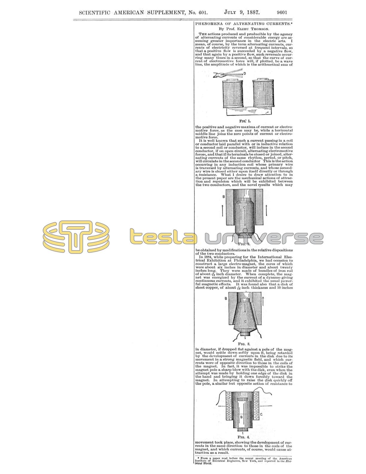
The experiment was, however, varied, as in Fig. 1. The disk, D, was held over the magnet pole, as shown, and the current in the magnet coils cut off by shunting them. There was felt an attraction of the disk or a dip toward the pole. The current was then put on by opening the shunting switch, and a repulsive action or lift of the disk was felt. The actions just described are what would be expected in such a case, for when attraction took place, currents had been induced in the disk, D, in the same direction as those in the magnet coils beneath it, and when repulsion took place the induced current in the disk was of opposite character or direction to that in the coils.
Now let us imagine the current in the magnet coils to be not only cut off, but reversed back and forth. For the reasons just given, we will find that the disk, D, is attracted and repelled alternately; for, whenever the currents induced in it are of the same direction with those in the inducing or magnet coil, attraction will ensue, and when they are opposite in direction, repulsion will be produced. Moreover, the repulsion will be produced when the current in the magnet coil is rising to a maximum in either direction, and attraction will be the result when the current of either direction is falling to zero, since in the former case opposite currents are induced in the disk, D, in accordance with well known laws, and in the latter case currents of the same direction will exist in the disk, D, and the magnet coil. The disk might, of course, be replaced by a ring of copper or other good conductor, or by a closed coil of bare or insulated wire, or by a series of disks, rings or coils superposed, and the results would be the same. Thus far, indeed, we have nothing of a particularly novel character, and, doubtless, other experimenters have made very similar experiments and noted similar results to those described.
The account just given of the effects produced by alternating currents, while true, is not the whole truth, and just here we may supplement it by the following statements:
An alternating current circuit or coil repels and attracts a closed circuit or coil placed in direct or magnetic inductive relation therewith; but the repulsive effect is in excess of the attractive effect.
When the closed circuit or coil is so placed, and is of such low resistance metal that a comparatively large current can circulate as an induced current, so as to be subject to a large self-induction, the repulsive far exceeds the attractive effort.
For want of a better name, I shall call this excess of repulsive effect the "electro-inductive repulsion" of the coils or circuits.
This preponderating repulsive effect may be utilized or may show its presence by producing movement or pressure in a given direction, by producing angular deflection as of a pivoted body, or by producing continuous rotation with a properly organized structure. Some of the simple devices realizing the conditions I will now describe.
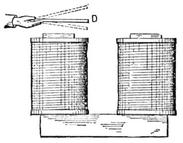
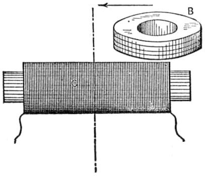
In Fig. 2, C is a coil traversed by alternating currents, B is a copper case or tube surrounding it, but not exactly over its center. The copper tube, B, is fairly massive and is the seat of heavy induced currents. There is a preponderance of repulsive action, tending to force the two conductors apart in an axial line. The part, B, may be replaced by concentric tubes slid one in the other, or by a pile of flat rings, or by a closed coil of coarse or line wire insulated, or not. If the coil, C, or primary coil, is provided with an iron core such as a bundle of fine iron wires, the effects are greatly increased in intensity, and the repulsion with a strong primary current may become quite vigorous, many pounds of thrust being producible by apparatus of quite moderate size.
The forms and relations of the two parts, C and B, may be greatly modified, with the general result of a preponderance of repulsive action when the alternating currents circulate.
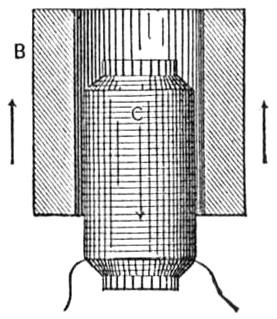
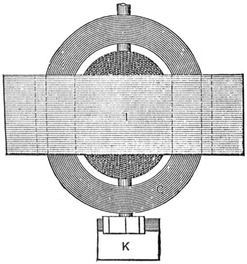
Fig. 3 shows the part, B, of an internally tapered or coned form, and C of an externally coned form, wound on an iron wire bundle, I. The action in Fig. 2 may be said to be analogous to that of a plain solenoid with its core, except that repulsion, and not attraction, is produced, while that of Fig. 3 is more like the action of tapered or conically wound solenoids and taper cores. Of course, it is unnecessary that both be tapered. The effect of such shaping is simply to modify the range of action and the amount of repulsive effort existing at different parts of the range.
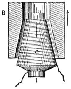
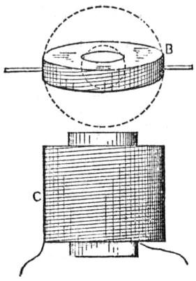
In Fig. 4 the arrangement is modified so that the coil, C, is outside, and the closed band or circuit, B, inside and around the core, I. Electro-inductive repulsion is produced as before.
It will be evident that the repulsive actions will not be mechanically manifested by axial movement or effort when the electrical middles of the coils or circuits are coincident. In cylindrical coils in which the current is uniformly distributed through all the parts of the conductor section, what I here term the electrical middle, or the center of gravity of the ampere turns of the coils, will be the plane at right angles to its axis at its middle, that of B and C, in Fig. 4, being indicated by a dotted line. To repeat, then, when the centers or center planes of the conductors, Fig. 4, coincide, no indication of electro-inductive repulsion is given, because it is mutually balanced in all directions; but when the coils are displaced, a repulsion is manifested, which reaches a maximum at a position depending on the peculiarities of proportion and distribution of current at any time in the two circuits or conductors.
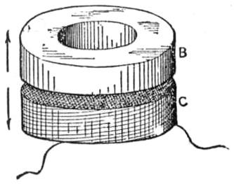
It is not my purpose now to discuss the ways of determining the distribution of currents and mechanical effects, as that would extend the present paper much beyond its intended limit. The forms and relative arrangement of the two conductors may be greatly varied. In Fig. 5 the parts are of equal diameter, one, B, being a closed ring, and the other, C, being an annular coil placed parallel thereto; and an iron core or wire bundle placed in the common axis of the two coils increases the repulsive action. B may be simply a disk or plate of any form, without greatly affecting the nature of the action produced. It may also be composed of a pile of copper washers or a coil of wire, as before indicated.
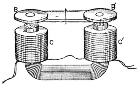
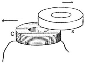
An arrangement of parts somewhat analogous to that of a horseshoe electro magnet and armature is shown in Fig. 6. The alternating current coils, C C', are wound upon an iron wire bundle bent into U form, and opposite its poles is placed a pair of thick copper disks, B B', which are attracted and repelled, but with an excess of repulsion depending on their form, thickness, etc.
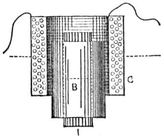
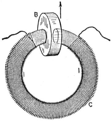
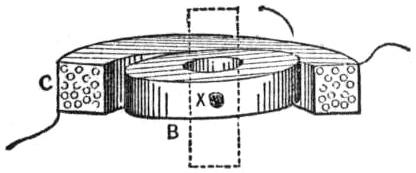
If the iron core takes the form of that shown by I I, Fig. 7, such as a cut ring with the coil, C, wound thereon, the insertion of a heavy copper plate, B, into the slot or divided portion of the ring will be opposed by a repulsive effort when alternating currents pass in C. This was the first form of device in which I noticed the phenomenon of repulsive preponderance in question. The tendency is to thrust the plate, B, out of the slot in the ring excepting only when its center is coincident with the magnetic axis joining the poles of the ring between which B is placed.
If the axes of the conductors. Fig. 5, are not coincident, but displaced, as in Fig. 8, then, besides a simple repulsion apart, there is a lateral component or tendency, as indicated by the arrows. Akin to this is the experiment illustrated in Fig. 9. Here the closed conductor, B, is placed with its plane at right angles to that of C, wound on a wire bundle. The part, B, tends to move toward the center of the coil, C, so that its axis will be in the middle plane of C, transverse to the core, as indicated by the dotted line. This leads us at once to another class of actions, i. e., deflective actions.
When one of the conductors, as B, Fig. 10, composed of a disk, or, better, of a pile of thin copper disks, or of a closed coil of wire, is mounted on an axis, X, transverse to the axis of coil, C, through which coil the alternating current passes, a deflection of B to the position indicated by dotted lines will take place, unless the plane of B is at the start exactly coincident with that of C. If slightly inclined at the start, deflection will be caused as stated. It matters not whether the coil, C, incloses the part, B, or be inclosed by it, or whether the coil, C, be pivoted and B fixed, or both be pivoted. In Fig. 11 the coil, C, surrounds an iron wire core, and B is pivoted above it, as shown. It is deflected, as before, to the position indicated in dotted lines.
It is important to remark here that in cases where deflection is to be obtained, as in Figs. 10 and 11, B had best be made of a pile of thin washers or a closed coil of insulated wire instead of a solid ring. This avoids the lessening of effect which would come from the induction of currents in the ring, B, in other directions than parallel to its circumference.
We will now turn our attention to the explanation of the actions exhibited, and afterward refer to their possible applications. It may be stated as certainly true that were the induced currents in the closed conductor unaffected by any self-induction, the only phenomena exhibited would be alternate equal attractions and repulsions, because currents would be induced in opposite directions to that of the primary current when the latter current was changing from zero to maximum positive or negative current, so producing repulsion; and would be induced in the same direction when changing from maximum positive or negative value to zero, so producing attraction.
This condition can be illustrated by a diagram, Fig. 12. Here the lines of zero current are the horizontal straight lines. The wavy lines represent the variations of current strength in each conductor, the current in one direction being indicated by that portion of the curve above the zero line, and in the other direction by that portion below it. The vertical dotted lines simply mark off corresponding portions of phase or succession of times.
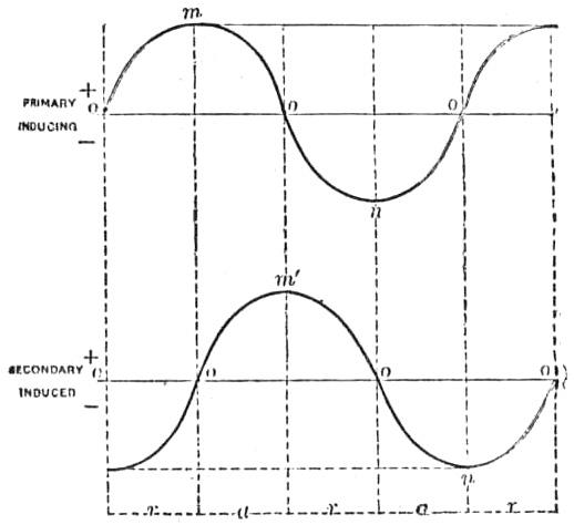
Here it will be seen that in the positive primary current descending from m, its maximum, to the zero line, the secondary current has risen from its zero to m1, its maximum. Attraction will therefore ensue, for the currents are in the same direction in the two conductors. When the primary current increases from zero to its negative maximum, n, the positive current in the secondary closed circuit will be decreasing from m1, its positive maximum, to zero; but, as the currents are in opposite directions, repulsion will occur. These actions of attraction and repulsion will be reproduced continually, there being a repulsion, then an attraction, then a repulsion, and again an attraction, during one complete wave of the primary current. The letters, r, a, at the foot of the diagram, Fig. 12, indicate this succession.
In reality, however, the effects of self-induction in causing a lag, shift, or retardation of phase in the secondary current will considerably modify the results, and especially so when the secondary conductor is constructed so as to give to such self-induction a large value. In other words, the maxima of the primary or inducing current will no longer be found coincident with the zero points of the secondary currents. The effect will be the same as if the line representing the wave of the secondary current in Fig. 12 had been shifted forward to a greater or less extent. This is indicated in diagram, Fig. 13. It gives doubtless an exaggerated view of the action, though from the effects of repulsion which I have produced, I should say it is by no means an unrealizable condition.
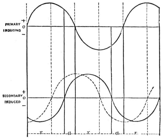
It will be noticed that the period during which the currents are opposite, and during which repulsion can take place, is lengthened at the expense of the period during which the currents are in the same direction for attractive action. These differing periods are marked r, a, etc., or the period during which repulsion exists is from the zero of the primary or inducing current to the succeeding zero of the secondary or induced current; and the period during which attraction exists is from the zero of the induced current to the zero of inducing current.
But far more important still in giving prominence to the repulsive effect than this difference of effective period is the fact that during the period of repulsion both the inducing and induced currents have their greatest values, while during the period of attraction the currents are of small amounts comparatively. This condition may be otherwise expressed by saying that the period during which repulsion occurs includes all the maxima of current, while the period of attraction includes no maxima. There is then a repulsion due to the summative effects of strong opposite currents for a lengthened period, against an attraction due to the summative effects of weak currents of the same direction during a shortened period, the resultant effect being a greatly preponderating repulsion.
It is now not difficult to understand all the actions before described as obtained with the varied relations of coils, magnetic fields, and closed circuits. It will be easily understood, also, that an alternating magnetic field is in all respects the same as an alternating current coil in producing repulsion on the closed conductor, because the repulsions between the two conductors are the result of magnetic repulsions arising from opposing fields produced by the coils when the currents are of opposite directions in them.
Thus far I have applied the repulsive action described in the construction of alternating current indicators, alternating current arc lamps, regulating devices for alternating currents, and to rotary motors for such currents. For current indicators, a pivoted or suspended copper band or ring composed of thin washers piled together and insulated from one another, and made to carry a pointer or index has been placed in the axis of a coil conveying alternating currents whose amount or potential is to be indicated. Gravity or a spring is used to bring the index to the zero of a divided scale, at which time the plane of the copper ring or band makes an angle of, say, 15 degrees to 20 degrees with the plane of the coil. This angle is increased by deflection more or less great, according to the current traversing the coil. The instrument can be calibrated for set conditions of use. Time would not permit of a full description of these arrangements: as made up to the present.
In arc lamps the magnet for forming the arc can be composed of a closed conductor, a coil for the passage of current, and an iron wire core. The repulsive action upon the closed conductor lifts and regulates the carbons in much the same manner that electro magnets do when continuous currents are used. The electro-inductive repulsive action has also been applied to regulating devices for alternating currents, with the details of which I cannot now deal.
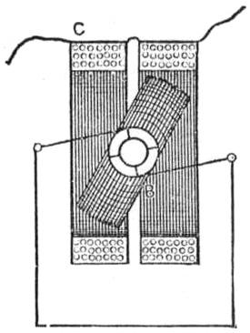
For the construction of an alternating current motor which can be started from a state of rest the principle has also been applied, and it may here be remarked that a number of designs of such motors is practicable.
One of the simplest is as follows: The coils, C, Fig. 14, are traversed by an alternating current and are placed over a coil, B, mounted upon a horizontal axis, transverse to the axis of the coil, C. The terminals of the coil, B, which is wound with insulated wire, are carried to a commutator, the brushes being connected by a wire, as indicated. The commutator is so constructed as to keep the coil, B, on short circuit from the position of coincidence with the plane of C to the position where the plane of B is at right angles to that of C; and to keep the coil, B, open-circuited from the right-angled position, or thereabouts, to the position of parallel or coincident planes. The deflective repulsion exhibited by B will, when its circuit is completed by the commutator and brushes, as described, act to place its plane at right angles to that of C; but being then open-circuited, its momentum carries it to the position just past parallelism, at which moment it is again short-circuited, and so on. It is capable of very rapid rotation, but its energy is small. I have, however, extended the principle to the construction of more complete apparatus. One form has its revolving portion or armature composed of a number of sheet iron disks wound as usual with three coils crossing near the shaft. The commutator is arranged to short-circuit each of these coils in succession, and twice in a revolution, and for a period of 90-degrees of rotation each. The field coils surround the armature, and there is a laminated iron field structure completing the magnetic circuit. I may say here that surrounding the armature of a dynamo by the field coils, though very recently put forth as a new departure, was described in various Thomson-Houston patents, and to a certain extent all Thomson-Houston machines embody this feature.
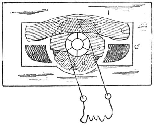
Figs. 15 and 16 will give an idea of the construction of the motor referred to. C C1 are the field coils or inducing coils, which alone are put into the alternating current circuit. I I is a mass of laminated iron, in the interior of which the armature revolves, with its three coils, B, B2, B3, wound on a core of sheet iron disks. The commutator short-circuits the armature coils in succession in the proper positions to utilize the repulsive effect setup by the currents which are induced in them by the alternations in the field coils. The motor has no dead point, and will start from a state of rest and give out considerable power, but with what economy is not yet known.
A curious property of the machine is that at a certain speed, depending on the rapidity of the alternations in the coil, C, a continuous current passes from one commutator brush to the other, and it will energize electro magnets and perform other actions of direct currents. Here we have, then, a means of inducing direct currents from alternating currents. To control the speed and keep it at that required for the purpose, we have only to properly gear the motor to another of the ordinary type for alternating currents, namely, an alternating-current dynamo used as a motor. The charging of storage batteries would not be difficult with such a machine, even from an alternating-current line, though the losses might be considerable.