Nikola Tesla Articles
Some Novel Inventions of Nikola Tesla
Most members of the electrical profession associate the name of Nikola Tesla with high-frequency and high-potential currents, and few are acquainted with the fact that he has also invented several novelties for use in other branches of the profession. It is of some of these extraneous productions that I purpose treating in the course of this paper.
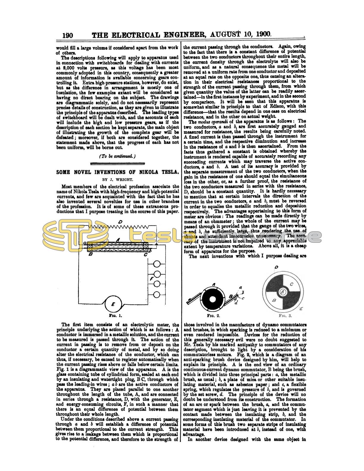
The first item consists of an electrolytic meter, the principle underlying the action of which is as follows: A conductor is immersed in a metallic solution, and the current to be measured is passed through it. The action of the current in passing is to remove from or deposit on the conductor a certain quantity of metal, and by so doing alter the electrical resistance of the conductor, which can thus, if necessary, be caused to register automatically when the current passing rises above or falls below certain limits. Fig. 1 is a diagrammatic view of the apparatus. A is the glass containing tube of cylindrical form, sealed at each end by an insulating and watertight plug, B C, through which pass the leading-in wires; a b are the active conductors of the apparatus. They are placed parallel to one another throughout the length of the tube, A, and are connected in series through a resistance, D, with the generator, E, and energy-consuming circuits, F, in such a manner that there is an equal difference of potential between them throughout their whole length.
Under the conditions described above a current passing through a and b will establish a difference of potential between them proportional to the current strength. This gives rise to a leakage between them which is proportional to the potential difference, and therefore to the strength of the current passing through the conductors. Again, owing to the fact that there is a constant difference of potential between the two conductors throughout their entire length, the current density through the electrolyte will also be uniform, and as a natural consequence the metal will be removed at a uniform rate from one conductor and deposited at an equal rate on the opposite one, thus causing an alteration in their electrical resistances proportional to the strength of the current passing through them, from which given quantity the value of the latter can be readily ascertained - in the first instance by experiment, and in the second by comparison. It will be seen that this apparatus is somewhat similar in principle to that of Edison, with this difference - that the results depend in one case on electrical resistance, and in the other on actual weight.
The modus operandi of the apparatus is as follows: The two conductors, a and b, are first accurately gauged and measured for resistance, the results being carefully noted. A fixed current is then passed through the instrument for a certain time, and the respective diminution and increase in the resistance of a and b is then ascertained. From the facts thus gathered a constant is obtained whereby the instrument is rendered capable of accurately recording any succeeding currents which may traverse the active conductors, a and b. A test of its accuracy is provided by the separate measurement of the two conductors, when the gain in the resistance of one should equal the simultaneous loss in the other, or, as a further proof, the resistance of the two conductors measured in series with the resistance, D, should be a constant quantity. It is hardly necessary to mention that at certain intervals the direction of the current in the two conductors, a and b, must be reversed in order to equalise the metallic reduction and deposition respectively. The advantages appertaining to this form of meter are obvious: The readings can be made directly by means of an ohmmeter; the whole of the current may be passed through it provided that the gauge of the two wires, a and b, be sufficiently large, thus rendering the use of shunts and attendant inaccuracies unnecessary. The accuracy of the instrument is not impaired to any appreciable extent by temperature variations. Above all, it is a cheap form of apparatus for the purpose.
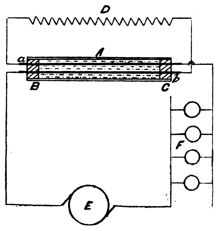
The next inventions with which I purpose dealing are those involved in the manufacture of dynamo commutators and brushes, in which sparking is reduced to a minimum or even rendered impossible. Devices for the reduction of this generally necessary evil were no doubt suggested to Mr. Tesla by his marked antipathy to commutators of any description, brought to light by a consideration of his commutatorless motors. Fig. 2, which is a diagram of an anti-sparking brush device designed by him, will help to explain its principle. A is the end view of an ordinary continuous-current dynamo commutator, B being the brash, which is divided into three principal parts: a, the metallic brush, as usual; b, a plate of mica or other suitable insulating material, such as asbestos paper; and c, a flexible spring, which regulates the pressure of b, and is governed by the set screw, d. The principle of the device will no doubt be understood from its construction. The formation of an arc or spark between the brush, a, and the commutator segment which is just leaving it is prevented by the contact made between the insulating strip, b, and the corresponding insulating material of the commutator. In some forms of this brush two separate strips of insulating material have been introduced at b, instead of one, with advantage.
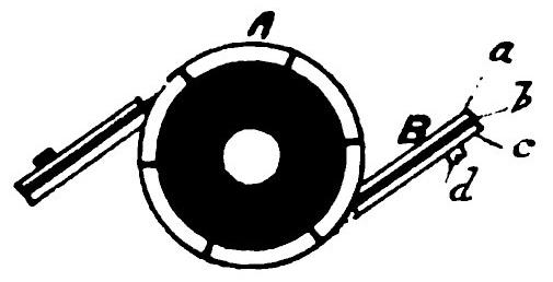
In another device designed with the same object in view - viz., the elimination of sparking between commutator segments and collectors - both apparatus take the form of discs with their faces well surfaced revolving accurately against one another. Fig. 3 is a diagrammatic end view of the commutator disc of one of these devices. A is the dynamo shaft; B and C are the metallic sectors; D and E the corresponding sectors of insulating material, this being only a simple two-part commutator. The whole surface of the disc in Fig. 3 is accurately faced and smoothed, so that both metallic and insulating sectors are flush with one another. The collector disc is the facsimile of that shown in Fig. 3, but is not keyed to the shaft of the dynamo.
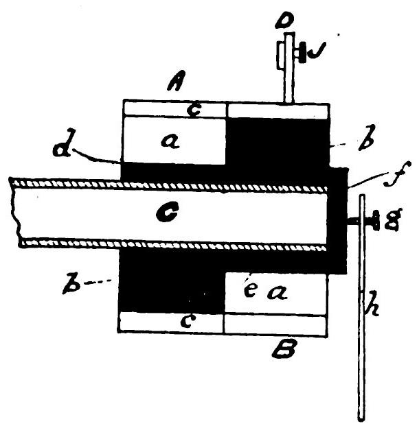
A general idea of the complete apparatus may be gained by a study of Fig. 4, which represents a longitudinal section of the commutator, A, and B, the collector; a a represent two metallic and b b two insulating sectors; c c are insulating rings which surround the outside edges of the sectors, and prevent a dissolution of partnership on the ground of centrifugal force; C is the dynamo shaft, through the tubular extremity of which are brought the wires from the armature coils; d is an insulating collar placed between the sectors and the shaft to prevent contact, and revolving with the latter; e is a similar insulating sleeve for the collector, and the dynamo shaft revolves inside it; a cap, f, is screwed on the end of this movable sleeve, and the pressure of a set screw, g, on the end of a stiff steel spring, h, serves to maintain good surface contact, between the commutator and collector surfaces; D is a quadrant for adjustment with a set screw, j, which takes the place of the ordinary brush-rocker, and serves to set the angle of the collectors. The advantages of this form of dynamo commutation will also be readily seen. The short-circuiting interval is reduced to a minimum by the simultaneous "make" and "break" of the sectors, which reduces sparking, besides increasing the efficiency of the machine.
In another form of the same device a liquid - mercury, to wit - takes the place of the solid metallic sectors. The two discs are built completely of insulating material in this case, and in place of the solid metallic sectors cavities are left in their faces. The terminals of the collector end in airtight spring plungers or buffers, which serve to regulate the pressure of the mercury under the action of centrifugal force, and also to ensure a good contact between it and the terminal screws. In both forms the insulating blocks should be constructed of some durable material, such as glass or marble, whilst in the solid form the efficiency and durability may be augmented by facing the edges of the metal segments, between which the major portion of the sparking would tend to take place with some durable conducting material, such as platinum.
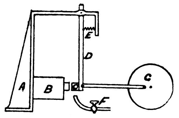
In the course of his electrical research, Tesla has not failed to study the subject of thermomagnetism, and as a result he constructed one or two rather ingenious forms of thermomagnetic motor, which are, however, for obvious reasons, still in an experimental stage. They are founded on the fact proved by Dr. William Gilbert at the beginning of the seventeenth century, that a magnet or lodestone when heated to redness is deprived of its magnetism. The principle underlying the device is illustrated in Fig. 5, in which A is a standard or support carrying a magnet, B, permanent or otherwise. C u an armature of the latter, forming the bob of a pendulum rod, D, supported above; E is a spiral spring which comes into play when the armature is demagnetised; F is a gas-burner or other suitable source of heat; and G is a wheel and connecting rod by which the power is converted into the ordinary form of rotary motion. Its action is as follows: The armature, C, is in the first instance attracted by the magnet against the tension of the spring, E. On heating C by means of the burner, F, it loses its magnetism and is drawn back by the spring out of the flame. On cooling, the magnetism again comes into play, and the armature returns to its original position, to be again heated, and so it goes on, the motion being of necessity somewhat slow.
There are several modifications of this motor, all working on the same main principle. In one the core of the electromagnet is made movable, and takes the place of the swinging armature, C, which is fixed. To the end of the magnet core it attached a shield, which, when the armature loses its magnetism and the core is drawn back by the spring in consequence, comes between the armature and the flame, and allows the former to cool by intercepting the heat rays. In another form the armature rocks over the two pole-faces of a permanent horseshoe magnet spanned by a sheet-iron keeper, which latter is heated by a burner whose tap valve is controlled by the rocking armature itself.
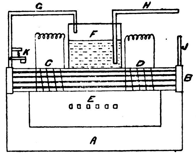
A study of the reverse of these conditions also led Mr. Tesla to construct a pyro-magnetic generator based on the undermentioned laws: "Electricity, or electrical energy, is developed in any conducting body by subjecting such body to a varying magnetic influence. The magnetic properties of iron or other magnetic material may be partially or entirely destroyed or caused to disappear by raising it to a certain temperature, but restored and caused to reappear by again lowering its temperature to a certain degree." Tesla's apparatus for practically applying these laws is represented diagrammatically in Fig. 6. A is a permanent magnet, the poles of which are bridged across by a casing containing a number of iron tubes, B. Bound this compound bridging-piece are wound the collecting coils, C and D, which serve to collect the current generated. E is a closed furnace surrounding the central portion of the bridging-piece, and surmounted by a boiler, F, the steam generated in which is conveyed to the tubes, B, in the bridging-piece by the pipe, G. H is the water-supply pipe, and J the exhaust. The admission of steam is regulated by a valve, K, under the control of the magnet A.
From the several inventions dealt with above, it will be seen that Mr. Tesla has not confined his labours solely to the field of high frequencies.