Nikola Tesla Articles
Tesla and Hertz Effects
The currents of high frequency used by Tesla in his researches are produced by electrical rather than mechanical means. The alternating current dynamo used by him renders a current of 10,000 alternations per second, but the actual current necessary to the performance of the luminous effects has a frequency of millions of oscillations per second, produced by the discharge of Leyden jars or condensers.
Dr. Oliver J. Lodge, in his "Modern Views of Electricity," shows that the discharge of the Leyden jar is in general oscillatory; the apparently single and momentary spark, when analyzed in a very rapidly rotating mirror, is shown to consist of a series of alternating flashes, rapidly succeeding one another and lasting individually less than one hundred thousandth of a second. The capacity of the condenser and inertia of the circuit regulate the rapidity of these oscillations. A 1 microfarad condenser discharging through a coil of large self-induction, such as one having an iron core, may oscillate only a few hundred times per second. On the other hand, a Leyden jar of the 1-pint size discharging through a short circuit will set up oscillations, perhaps ten million per second; and a still smaller jar would give oscillations away up in the billions. But these small jars are quickly discharged, and require a constant replenishing.
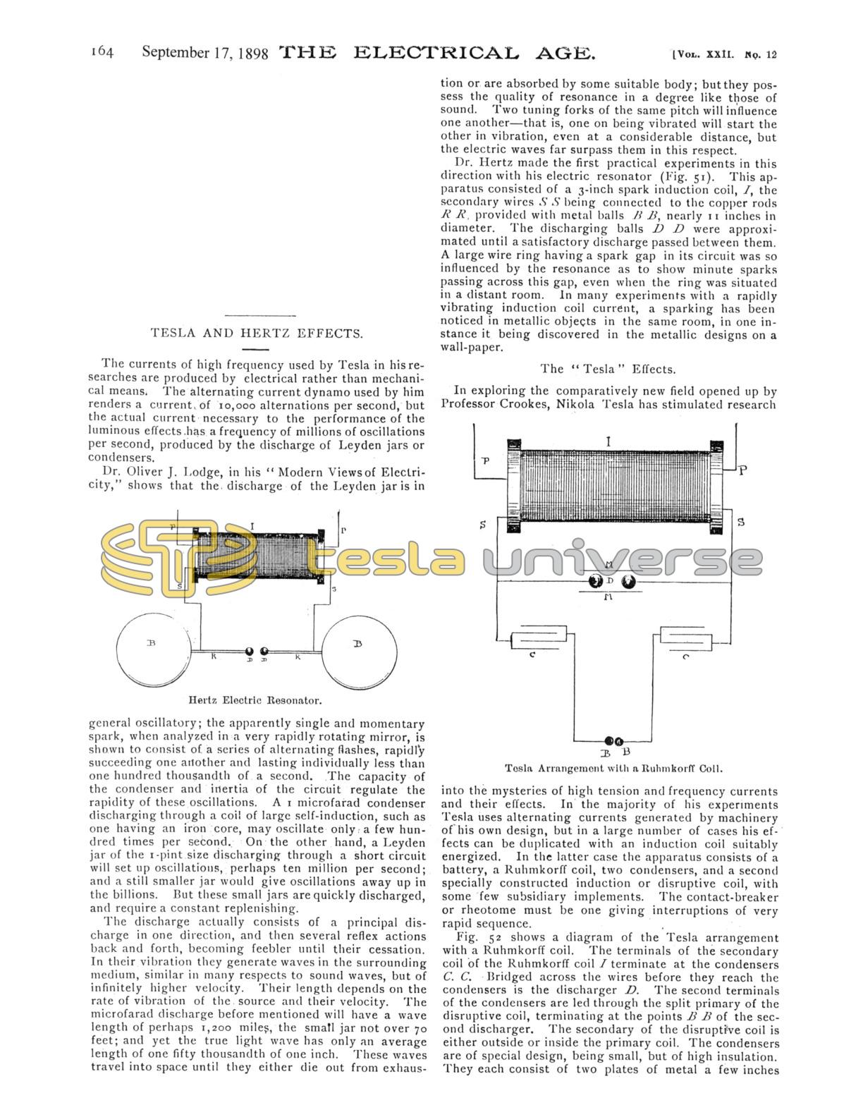
The discharge actually consists of a principal discharge in one direction, and then several reflex actions back and forth, becoming feebler until their cessation. In their vibration they generate waves in the surrounding medium, similar in many respects to sound waves, but of infinitely higher velocity. Their length depends on the rate of vibration of the source and their velocity. The microfarad discharge before mentioned will have a wave length of perhaps 1,200 miles, the small jar not over 70 feet; and yet the true light wave has only an average length of one fifty thousandth of one inch. These waves travel into space until they either die out from exhaustion or are absorbed by some suitable body; but they possess the quality of resonance in a degree like those of sound. Two tuning forks of the same pitch will influence one another - that is, one on being vibrated will start the other in vibration, even at a considerable distance, but the electric waves far surpass them in this respect. Dr. Hertz made the first practical experiments in this direction with his electric resonator (Fig. 51). This apparatus consisted of a 3-inch spark induction coil, I, the secondary wires S S being connected to the copper rods R R, provided with metal balls B B, nearly 11 inches in diameter. The discharging balls D D were approximated until a satisfactory discharge passed between them. A large wire ring having a spark gap in its circuit was so influenced by the resonance as to show minute sparks passing across this gap, even when the ring was situated in a distant room. In many experiments with a rapidly vibrating induction coil current, a sparking has been noticed in metallic objects in the same room, in one instance it being discovered in the metallic designs on a wall-paper.
The "Tesla" Effects
In exploring the comparatively new field opened up by Professor Crookes, Nikola Tesla has stimulated research into the mysteries of high tension and frequency currents and their effects. In the majority of his experiments Tesla uses alternating currents generated by machinery of his own design, but in a large number of cases his effects can be duplicated with an induction coil suitably energized. In the latter case the apparatus consists of a battery, a Ruhmkorff coil, two condensers, and a second specially constructed induction or disruptive coil, with some few subsidiary implements. The contact-breaker or rheotome must be one giving interruptions of very rapid sequence.
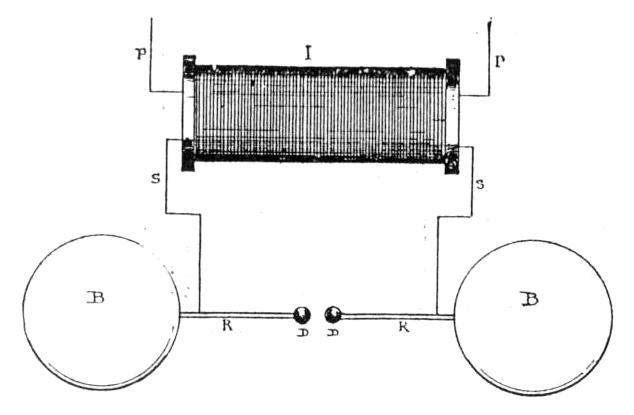
Fig. 52 shows a diagram of the Tesla arrangement with a Ruhmkorff coil. The terminals of the secondary coil of the Ruhmkorff coil I terminate at the condensers C. C. Bridged across the wires before they reach the condensers is the discharger D. The second terminals of the condensers are led through the split primary of the disruptive coil, terminating at the points B B of the second discharger. The secondary of the disruptive coil is either outside or inside the primary coil. The condensers are of special design, being small, but of high insulation. They each consist of two plates of metal a few inches square immersed in oil and arranged so they can be brought nearer together or further apart, as necessary. Within limits, the smaller these plates are the more frequent will be the oscillations of their discharge. They also fulfil another purpose; they help nullify the high self-induction of the secondary coil by adding capacity to it.

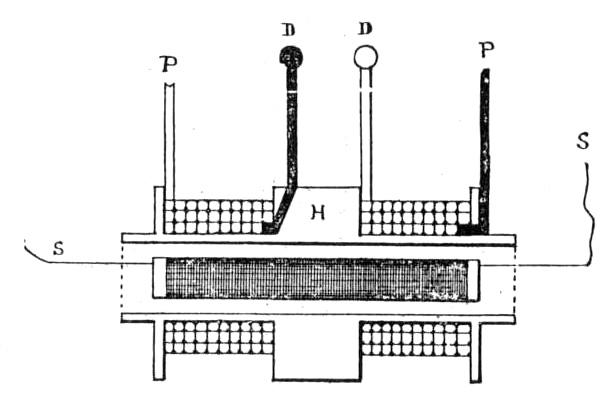
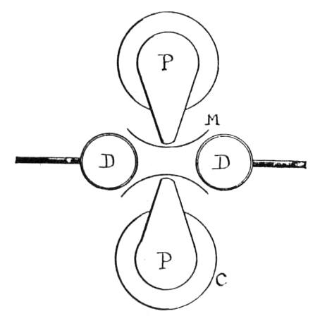
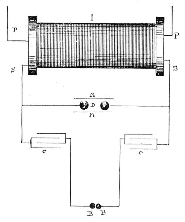
The discharger tips are preferably metal balls under 1 inch in diameter. Tesla uses various forms of dischargers, but for experimental purposes the two metal balls will answer. They are adjusted when the whole apparatus is working according to the results desired. The mica plates serve to establish an air current up through the gap, making the discharge more abrupt, an air blast being also used at times for the furtherance of this object. The device (Fig. 53) consists of an electro-magnet, C, set with its poles P across the air gap, helping to wipe out the spark, as in a well-known form of lightning arrester. This form, described by Tesla, has the pole pieces P shielded by mica plates M to prevent the sparks jumping into the magnets. Fig. 53 is an elevation and Fig. 54 a plan of this device. The terminals from the condenser are led to the primary of the disruptive coil, or, as in Fig. 52, to two discharger balls B B. The disruptive coil (Fig. 55) is easily made, and will give good results with careful handling.
The secondary coil S of 300 turns of No. 30 silk-covered magnet wire, wound on a rubber tube or rod ½ inch in diameter, with the ends brought out in glass or rubber tubes. The primary coils are wound on a second rubber tube, H, at least 1-10 inch thick, and large enough inside to slip easily over the secondary coil S. It must be long enough to project 2 or 3 inches over the ends of the secondary coil turns. The primary has 50 turns in each coil of No. 18 B. & S. gutta-percha covered wire. The four ends, P P P P, of this coil are brought out in rubber or glass tubes, two to the condenser and two to the discharger D D. Each layer of these coils must be separated by rubber cloth or even cotton cloth. The further apart the layers the less the inductive effect, but the better the insulation. The whole coil is immersed in a glass or wooden vessel containing boiled-out linseed or petroleum oil. A perfect coil should have all the air bubbles drawn out of it after being immersed by putting it under an air-pump, but for many experimental uses this is not absolutely necessary; but extreme care must be taken to insulate the coils and their terminals. This will be apparent when the current is turned on.
The resonance effects obtained during the operation of a Tesla coil are very marked, and their study may lead to the solution of the problems of communication between distant points without the use of other conducting media than the atmosphere. But the main use to which the Tesla currents have been put is that of artificial illumination. These currents have enabled experimenters to obtain a high luminosity in vacua by the aid of only one conducting wire - in fact, in some cases without the utilization of any conductor than the air. An ordinary incandescent lamp connected to one terminal of the coil will show in a fair degree some of the luminescent phenomena. The brush effects from the terminals of the secondary coils are extremely marked and interesting; but to detail the experiments that can be performed with the Tesla disruptive coil would be an impossibility here. Reference is recommended to the published works of Nikola Tesla, which, happily, are readily procurable.
These currents of high frequency have of late been turned to account in electro-therapeutics, principally for the stimulation they exert on the nutritive process. They also exert a very great influence on the vasomotor centres, as is evidenced by the reddening of the skin and exudation of perspiration. This result is readily obtainable by placing the patient in connection with one electrode on an insulating stool, and terminating the other electrode at a large metal plate situated a few feet distant; or the patient may be surrounded by a coil of wire in connection with the coil of sufficient diameter, however, to prevent contact. - H. S. Norrie, in "Ruhmkorff Induction Coils," by permission of Spon & Chamberlain.