Nikola Tesla Articles
Tesla Motors Operated from Single-Phase Two-Wire Alternating Circuits
Those who have followed Mr. Tesla's work in alternating motors will recall that in 1888 he first drew public attention to his new multiphase system of operating alternating current motors, in a paper read before the American Institute of Electrical Engineers, in which he laid down the principles which have since been practically applied in many ways. In this system, it will be remembered, each motor contains two or more independent energizing circuits through which are passed alternating currents, having in each circuit such a difference of phase that by their combined or resultant action they produce a rotary progression of the poles or points of maximum magnetic effect of the motor and thereby maintain the rotation of the armature.
A multiphase system of this kind, however, requires at least three wires for its successful operation, to convey the currents differing in phase, and Mr. Tesla, therefore, early set about to devise means for operating phase motors from the ordinary single phase alternating circuit, by creating the difference of phase locally at and in the motor. The various ways in which this can be done are described in two patents just granted to Mr. Tesla, which are of special interest at this time.
In all the methods described below the fundamental idea involved is to pass a single alternating current through both of the energizing circuits of the motor, and to retard the phase of the current in one circuit to a greater or less extent than in the other. The distribution of current between the two motor circuits is effected either by induction or by derivation.
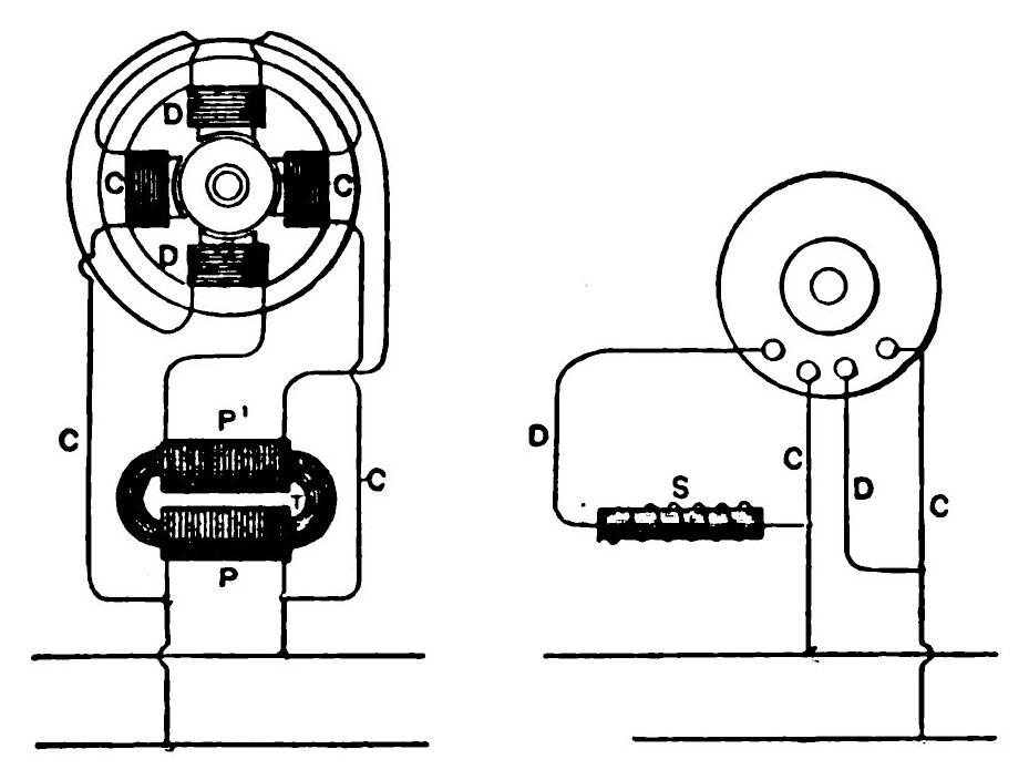
The diagram Fig. 1 shows a motor with two energizing circuits, C and D. One of these circuits, C, is connected directly with the line circuit, while the other set of coils, D, is connected up in the secondary circuit of a transformer, T. The primary coil, P, of this transformer is connected to the line circuit. The alternations of current in the line tend to establish in their passage through the coils, C, a polarity opposed to that set up in the coils, D, and if the currents in the two sets of coils coincided in their phases, no rotary effect would be produced. But the secondary current developed in the coil, P, of the transformer, will lag behind that in the primary, which lag may be increased to a sufficient extent to practically obtain the same result as though two independent currents were used to energize the motor.
In another form, shown in Fig. 2, the arrangement of the parts is similar to that shown in Fig. 6, except that a self-induction coil, S, is introduced into one energizing circuit of the motor. The effect of thus increasing the self-induction in one of the circuits is to retard the phases of the current passing therein to a greater extent than in the other circuit, and in this way to secure the necessary difference in phase between the two energizing currents to produce the rotation of the motor.
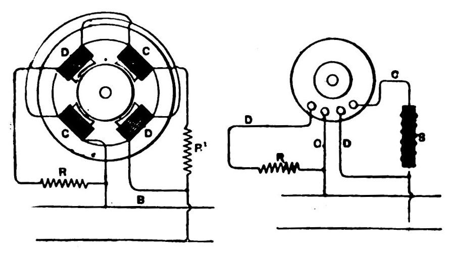
In Fig. 8 there is shown diagrammatically a type of motor in which two dead resistances, R R' , are included respectively in the energizing coils of the motor. No rotary effect will be produced as long as the resistances are equal, but by varying the resistance in one circuit the retardation of the current in that circuit will be varied and corresponding effects produced. For example, a reduction of the resistance in one circuit imparts to the motor rotation in one direction, while a reduction of the resistance in the other circuit will produce a rotation in the opposite direction. By means of the two resistances, therefore, capable of variation or of being bodily withdrawn from or inserted in the circuits by simple means, rotation of the motor is secured.
In Fig. 4 a self-induction coil, S, is included in one of the motor circuits and a dead resistance, R, in the other. The increased self-induction in one circuit thus produced acts to increase the difference of phase between the current in that motor circuit and the unretarded current in the line circuit On the other hand, the introduction of the dead resistance in the other motor circuit reduces the retardation and brings the phases of the current in it more closely in accord with those of the unretarded current, thus producing a correspondingly greater difference of phase between the two currents in the energizing circuits, C and D.
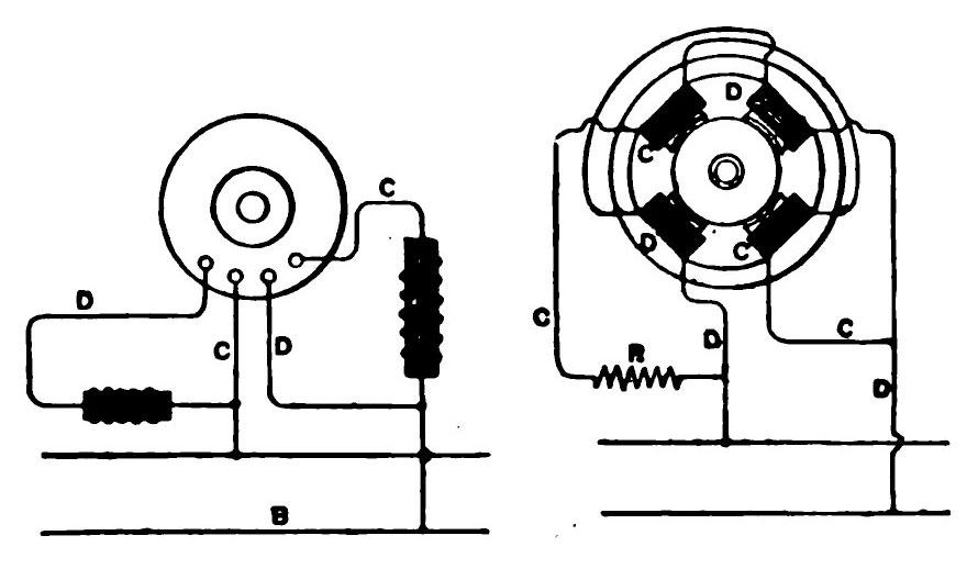
In Fig. 5, two self-induction coils are shown, one in each motor or energizing circuit. One of these coils is much smaller than the other and has less self-induction or counter E. M. F. than the other, so that the phases of current will be retarded to a less extent than in the other.
In Fig. 6 the two energizing circuits of the motor are shown connected in multiple arc to the line circuit, and in one of these circuits is a resistance, R. Assuming the two motor circuits to have the same degree of self-induction, no rotary effect will be produced by the passage through them of an alternating current from the line. But if one of the motor circuits, as C, be varied or modified by the introduction of a dead resistance, R, the self-induction of that circuit or branch is reduced, and the phases of current therein retarded to a correspondingly less extent. The relative degrees of retardation of the phases of the current in the two motor circuits with respect to those of the unretarded current in the circuit, B, thus produced, will set up a rotation of the motor.
Finally we may mention another type in which one set of energizing coils is of finer wire than the other or has a greater number of convolutions, or each circuit may contain the same number of convolutions, but composed of different conductors, as, for instance, one of copper, and the other of German silver.
Mr. Tesla has devised still other methods for accomplishing the same purpose, but those described will give a fair idea of the wonderful flexibility of the system. - Electrical Engineer.
