Nikola Tesla Articles
Tesla Polyphase Induction Motors
Alternating current motors, although developed and perfected much later than direct current motors, were soon recognized to possess such great practical advantages that they have by rapid strides largely supplanted the latter in many important applications. They have, in fact, done more; being advantageously used in places where electric power could not be previously employed by reason of some of the inherent characteristics of direct current apparatus.
Alternating current apparatus, owing to the field which it originally occupied, was for a long time looked upon by many as applicable only to the transmission of power over long distances. The extreme simplicity and flexibility of the alternating system, however, added to the attractions of the polyphase motor, have led to the use of polyphase apparatus for the distribution of power in factories, mills, mines, and other industrial establishments where the distances are comparatively short. A large factor in the present popularity of alternating current power is due to the high state of perfection to which the improved polyphase motors have been brought; yet despite their practically exclusive use on all power transmissions, a knowledge of their mode of construction and principles of operation are not commonly understood. To give needed information on these points may best be done by describing distinctive forms of apparatus, for which the type "C" motor of the Tesla polyphase system, as brought out by the Westinghouse Electric and Manufacturing Company, is first selected for illustration and description. Tesla polyphase induction motors have two main elements; viz.: the primary, which is directly magnetized by the currents supplied from the line circuits; and the secondary, in which low potential currents are induced by the action of the primary. The windings of the primary are so arranged that when supplied with alternating currents differing in phase; i. e., polyphase currents, a rotating magnet field is produced. This field acts upon the secondary winding and induces currents therein. Rotation is produced by the action between the secondary currents and the rotating field of the primary. The principle upon which motors of this class operate was discovered by Mr. Nikola Tesla, whence their name.
The revolving element of an induction motor may be either the primary or the secondary. In the motors described herein, the primary is stationary and the secondary revolves; hence, for purposes of comparison, the primary may be regarded as corresponding to the field magnets, and the secondary as corresponding to the armature of a direct current motor.
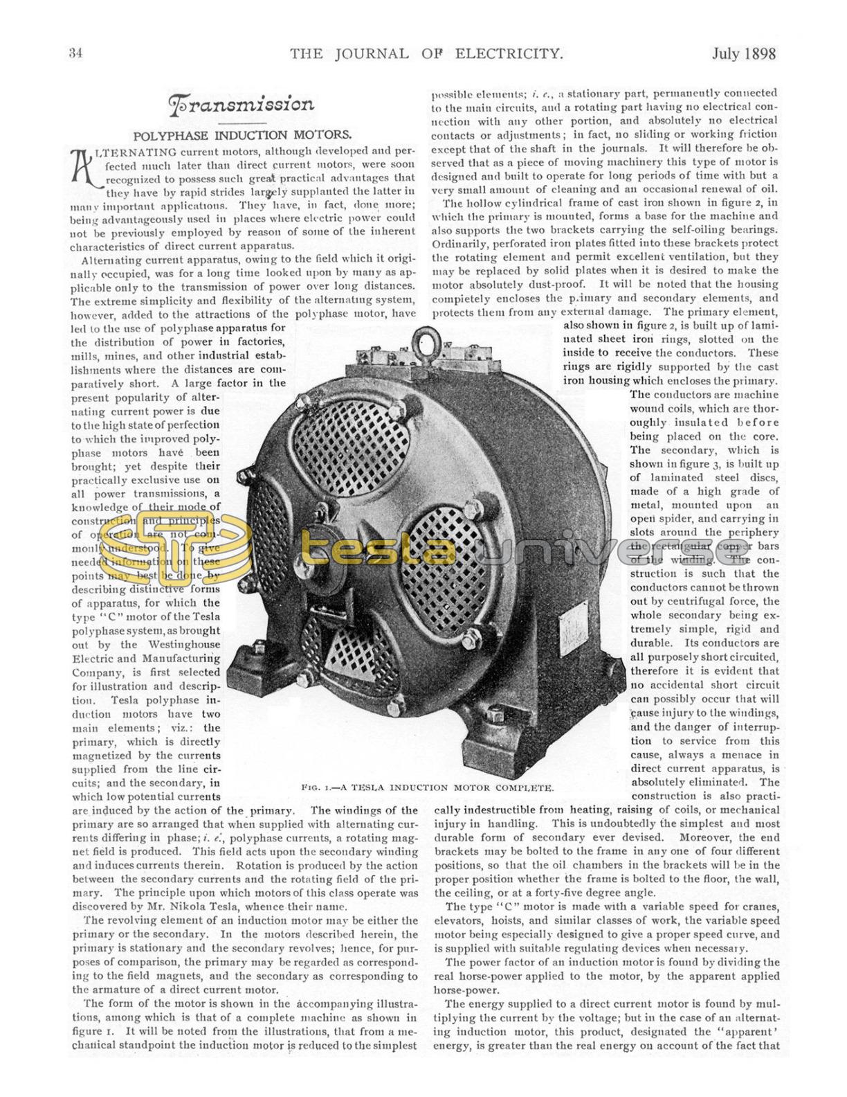
The form of the motor is shown in the accompanying illustrations, among which is that of a complete machine as shown in figure 1. It will be noted from the illustrations, that from a mechanical standpoint the induction motor is reduced to the simplest possible elements; i. e., a stationary part, permanently connected to the main circuits, and a rotating part having no electrical connection with any other portion, and absolutely no electrical contacts or adjustments; in fact, no sliding or working friction except that of the shaft in the journals. It will therefore be observed that as a piece of moving machinery this type of motor is designed and built to operate for long periods of time with but a very small amount of cleaning and an occasional renewal of oil.
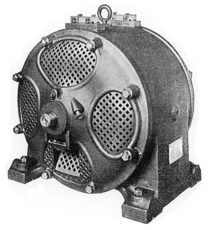
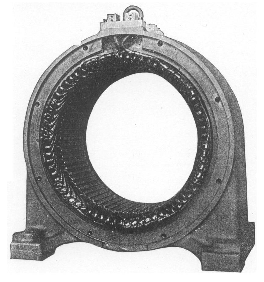
The hollow cylindrical frame of cast iron shown in figure 2, in which the primary is mounted, forms a base for the machine and also supports the two brackets carrying the self-oiling bearings. Ordinarily, perforated iron plates fitted into these brackets protect the rotating element and permit excellent ventilation, but they may be replaced by solid plates when it is desired to make the motor absolutely dust-proof. It will be noted that the housing completely encloses the primary and secondary elements, and protects them from any external damage. The primary element, also shown in figure 2, is built up of laminated sheet iron rings, slotted on the inside to receive the conductors. These rings are rigidly supported by the cast iron housing which encloses the primary. The conductors are machine wound coils, which are thoroughly insulated before being placed on the core. The secondary, which is shown in figure 3, is built up of laminated steel discs, made of a high grade of metal, mounted upon open spider, and carrying in slots around the periphery the rectangular copper bars of the winding. The construction is such that the conductors cannot be thrown out by centrifugal force, the whole secondary being extremely simple, rigid and durable. Its conductors are all purposely short circuited, therefore it is evident that no accidental short circuit can possibly occur that will cause injury to the windings, and the danger of interruption to service from this cause, always a menace in direct current apparatus, is absolutely eliminated. The construction is also practically indestructible from heating, raising of coils, or mechanical injury in handling. This is undoubtedly the simplest and most durable form of secondary ever devised. Moreover, the end brackets may be bolted to the frame in any one of four different positions, so that the oil chambers in the brackets will be in the proper position whether the frame is bolted to the floor, the wall, the ceiling, or at a forty-five degree angle.
The type "C" motor is made with a variable speed for cranes, elevators, hoists, and similar classes of work, the variable speed motor being especially designed to give a proper speed curve, and is supplied with suitable regulating devices when necessary.
The power factor of an induction motor is found by dividing the real horse-power applied to the motor, by the apparent applied horse-power.
The energy supplied to a direct current motor is found by multiplying the current by the voltage; but in the case of an alternating induction motor, this product, designated the "apparent" energy, is greater than the real energy on account of the fact that the current in such large motors "lags" behind the electromotive force, and hence the useful effect is less than would be the case if the current and electromotive force were coincident in phase. The current, however, exerts its full heating effect upon the conductors, and the excess current causes a corresponding drop of potential in the circuit. It is therefore desirable to reduce the lag as much as possible; i. e., to bring the real and apparent energies to coincide as near as we can. If it were possible to entirely eliminate the lag, the real and apparent horse-power would be equal, and the power factor would be 100. Special attention has been given to this matter in the designing of these machines, with the result that their power factors are very high.
The designs and principles governing the construction of the type "C" motor are fortunately favorable to a particularly attractive feature; i. e., the maintaining of a high and almost constant efficiency from full load to one-half load. Under the conditions which prevail in a very large proportion of electric motor service, the motors are operated much of the time at considerably less than their full rated capacities. With the type "C" motor, therefore, by maintaining a constant efficiency, there can be secured to the user an all day or average efficiency very much above that heretofore possible, with either direct or alternating current motors. The variation of speed between no load and full load is small, being less than that found in direct current motor practice.
A polyphase induction motor may be started by connecting it directly to the circuit with an ordinary switch, and small motors are so started in practice. The larger motors, however, are started on a reduced voltage, the full electromotive force of the circuit not being applied until the motors have reached a considerable speed.
In the Westinghouse system, the low electromotive force is ordinarily obtained by the auto-starter, shown on page 37, and which consists of a double throw switch mounted on a cast-iron box in which are two auto-converters. When the switch is closed in the position shown in the cut, the auto-converters are connected across the circuits and deliver a low electromotive force to the motor, but when the switch is thrown in the opposite direction the auto-converters are cut out and the motor is connected directly to the circuit. Three or four wires are connected directly to the auto-starter, and the same number of wires connect the auto-starter to the motor. The auto-converters are arranged with loops so that one of several voltages may be applied for starting, thus adjusting the torque for the work the motor has to do. Thus a motor operating a machine having great inertia may be made to give a correspondingly strong starting torque, or one driving a light device may be adjusted for extremely light starting torque with a corresponding reduction of current.
On two-phase circuits in which there are four wires, different electromotive forces exist between the different pairs of wires, and in some cases this affords a simple way of obtaining a low electromotive force for starting. A simple double throw switch is required, by which the low electromotive force for starting is obtained by one connection, and the full electromotive force for running by throwing the switch to the opposite position.
When it is necessary to install motors in a grain elevator, a woolen mill, a mine, or in any place exposed to inflammable gases or floating particles, or not easily accessible, the starting devices may be located at a convenient point more or less remote from the motor, thus eliminating all danger from fire due to possible sparks.