Nikola Tesla Articles
Waltham Speedometer
World's Largest Watch Maker Develops Air-Friction Instrument — Deliveries Started
The Waltham Watch Co., which five years ago took up the manufacture of automobile clocks and has since been marketing a complete line of these for motor cars and trucks, has further invaded the automobile field by the development of a new-principle speedometer, which it is about to start making deliveries of to automobile manufacturers. The company has taken up the development of this speedometer in the same systematic manner it did its automobile time pieces and has already organized a large department in its factory, the largest watch factory in the world, where it assembles all parts of the speedometer. These parts are being manufactured in the different departments of the watch factory, and watch standards of accuracy are applied to them. The development of this speedometer was started in the experimental department of the Waltham company three years ago and it has been going through the evolutionary stages since. The engineering departments of several large car builders have been utilized in a consulting capacity during this development stage. The instrument is to-day not an untried experiment but a known quantity and several manufacturers have been using it on test cars for months.
Production has already begun and the first lot of 25,000 is going through. The Waltham speedometer has been developed and is being manufactured to meet the demands of quality car builders yet lends itself to application on cars of all prices. That the Waltham company has entered the speedometer field in earnest is attested by the fact that negotiations are already well advanced for a country-wide selling and service system. The speedometer is being sold and guaranteed by the Waltham Watch Co. The Waltham speedometer will be sold separately or in various combinations with its time pieces.
The Waltham speedometer is an air- friction type and introduces a principle new in speed measuring and one which has not been previously used in any form of instrument. This speed-measuring part of the speedometer consists of two essentials called cups, one inverted and telescoping the other, with an air gap separating them. The driving cup is driven by a flexible shaft from the road wheel or transmission system. The driven cup, known as the indicating one, is inverted outside the driving cup. It is the air friction generated in the annular air space between the cups which constitutes the speed measuring medium of the instrument.
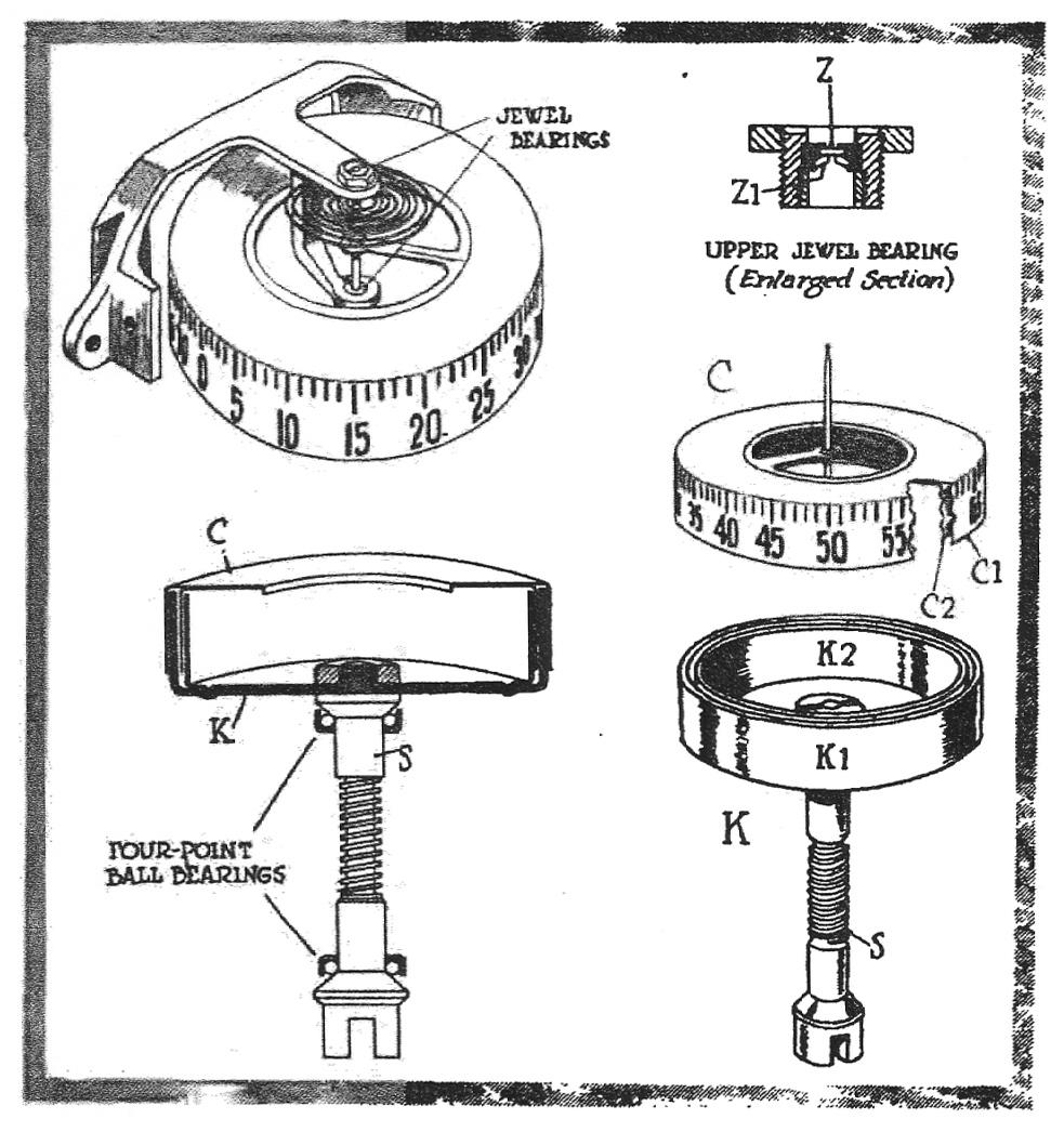
The relationship of these two cups is best shown in the lower right, Fig. 3. Each cup is in reality a double cup. Thus the revolving cup, K, consists of two concentric brass cups, K1 and K2, having an annular space 0.108 cm. between the two vertical walls called ribs for convenience. The cups K and K1 are rigidly mounted on the vertical shaft S so that when one revolves both revolve.
The driven or indicating cup C consists of two aluminum cups C1 and C2 attached together so that to all intents and purposes they form a single cup. These cups are extremely light, being made of aluminum 8/1000 of a centimeter thick. This means that 313 of these cup thicknesses would be required to make 1 in.
The aluminum cup C when in position in the instrument has the inner rib C2 floating in the annular space between the ribs K1 and K2 of the brass cup. The outer rib C1 of the aluminum cup floats outside of the brass rib K1. There is an air space at all times of one-half millimeter between the ribs of the brass and aluminum cups. On the outer face of the aluminum cup are the calibration figures to indicate the speed in miles per hour.
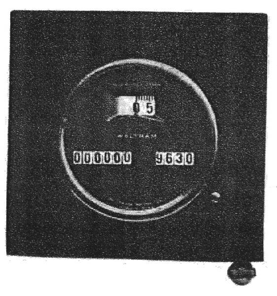
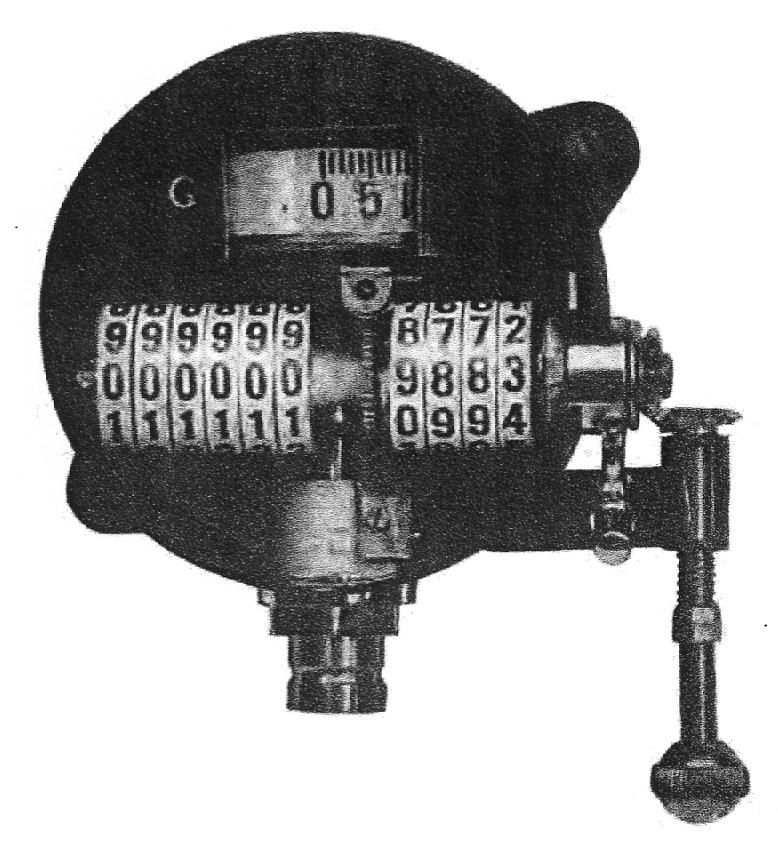
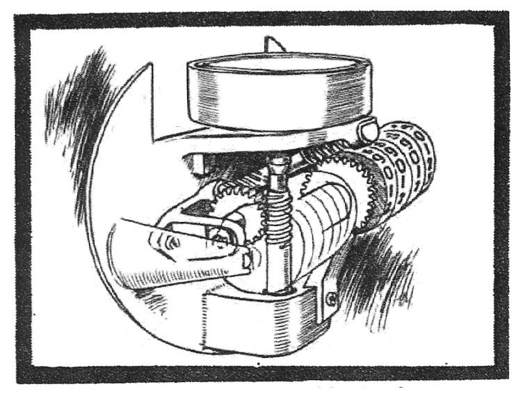
Fig. 2 is a photographic reproduction of the interior of the speedometer with the dial removed and shows how the aluminum cup telescopes the brass cup. The revolving of the brass cup generates the air friction which would revolve the aluminum cup also were it not for a regulating hair spring shown in the upper left, Fig. 3. This hair spring is so adjusted as to permit the correct oscillation of the indicating cup according to the speed. This regulation between the hair spring and the tendency to rotate is so accurate that the instrument indicates immediately all speed changes, and indicates as low as one-half mile per hour.
The principle of air friction between revolving concentric cups has been proved to be directly in proportion to the speed of the revolving cup, in this case the driven brass cup. It is this fact that makes a uniform calibration possible without adding compensating devices to gain this end. The principle of indicating speed through air friction is covered by patents controlled by the Waltham company. Comprehensive laboratory tests have proved that air friction is not influenced by heat, cold, or altitude up to 10,000 ft. The revolving cups have not to be carried in an air-tight compartment, and no sealing is necessary.
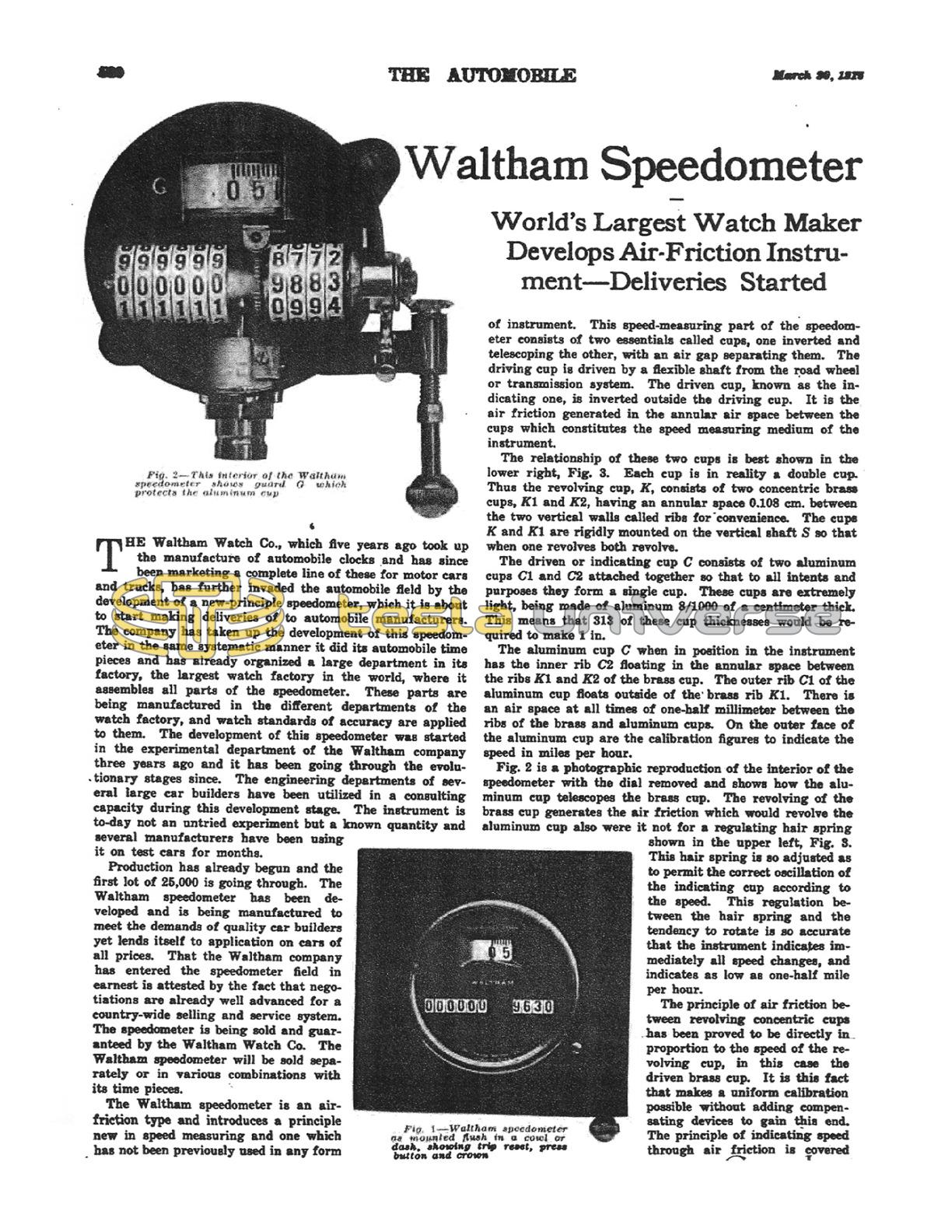
Incorporated in the instrument, Fig. 2, are season and trip odometers, both characterized by having particularly large figures spaced closely together. The odometer figures are black excepting those indicating tenths, which are red on both the trip and season. The trip odometer registers up to 999.9 miles and the season odometer to 99,999.9 miles and repeats. A quick reset device for the trip odometer is featured and appears in Fig. 1. Close to the dial is a press button and adjacent to it a reset crown. By turning the crown, or ball, and without pressing the button you can reset the tenths and total trip; but by pressing the button also you can reset the entire trip mileage ten times as fast.
The separate indicating wheels in the trip and season odometer are placed close together which makes it possible to use large figures. This placing of these wheels so is made possible by the use of an internal sun-and-planet gear drive between adjacent wheels.
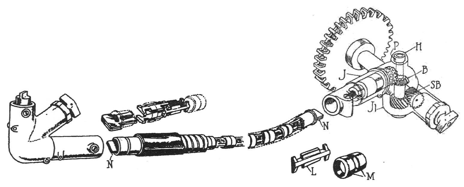
In every speedometer what is known as the head incorporating the odometer and speed measuring device, constitutes one part of the instrument and the second and equally important part is made up of the flexible shaft together with other fittings including swivel joint, angle joint, etc., Fig. 4. The Waltham company has given as much attention to this second part of the instrument. The flexible shaft is a patented design of the company, and is made up of a series of interlocking links L held in position by a series of steel collars M so that it is impossible for the links to come apart. The chain is assembled from one end to the other and it is impossible to take it apart in the middle or at any other point except from either end. No rivets are employed in it, and it is such that it can be assembled or taken apart by an inexperienced workman without the aid of any tools and in a very short time. The only tool necessary in dismantling the chain is a pair of pliers to remove the locking male member N in the driving connection at either end. This done the entire linkage can be taken apart. All of the links L are heat treated nickel steel stampings. The collars M are of the same material. Surrounding the chain thus formed is the usual flexible casing with a leather cover as optional.
The swivel joint at the driving end of the flexible shaft is a Waltham design. Gears and shafts are heat treated. Ball bearings are used. The swivel joint consists of two, a pair of spiral bevels SB and a pair of bevel gears B. A feature of this swivel is the quick means of dismantling, in that the housing cap H is snapped in position and when removed permits of removing the pin P from the retaining collar on the top of the shaft. This done the entire housing J is removed, leaving the vertical shaft carried on the lower part of the housing J1. A large capacity grease cup is an integral portion of the swivel joint.
In designing the driving mechanism the Waltham company has endeavored to have the swivel joint, shaft, and shaft casing, interchangeable with other standard instruments. The revolving brass cups K, Fig. 3, must revolve 1008 times to the mile. With the aid of gear ratios in the angle joint or swivel joint, Fig. 4, the flexible shaft may revolve at either 680 or 1008.
The assembly of the head of the Waltham speedometer is such that the complete group illustrated in Fig. 5 is placed within the case or shell as a unit. With this unit goes a guard for the indicating aluminum cup shown in another illustration. The dial showing ear speed as well as trip and season odometer is commendably plain, making it correspondingly easy to see the large indicating figures.