Nikola Tesla Letters
September 22nd, 1899 letter from Nikola Tesla to George Scherff
Colorado Springs, Sept. 22, 1899
Dear Mr. Scherff,
Czito has just arrived and I was glad to see a familiar face again. He looks a little too fat for the work I expect of him. Please tell Mr. Uhlman to prepare as quickly as possible an apparatus to the following description. A clockwork same as the last two sent in every particular except there will be no "Unruhe", and on the small quick moving pinion there will be a fan with adjustable wings of aluminum. I find the fan is easiest made as in sketch of a small light brass bushing a with hole o to fit on shaft of pinion, and screws s s, one on each side with light washers to hold down the wings of aluminum, slotted partly to allow the screw to pass through for purpose of adjustment, and fastening in position.
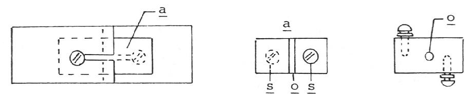
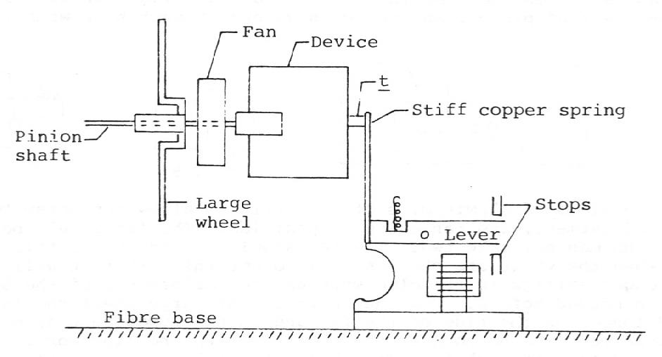
The fan should be as light as possible. Mr. Uhlman may make two. The fan should retard very little and should spin very fast when the wings are shortest. I do not think that it will be necessary to put in stronger springs in the clockwork as the performance of the springs is much smaller than needed before. Now the shaft of the large wheel should be as strong as before and longer on the side of the fan and on the opposite side a copper contact spring should be fixed to connect shaft surely with the clockwork. No spring of this kind is needed on pinion shaft. The shaft of the large wheel will carry on the fan side a device similar to those of which a number were sent to me, only I shall want this device a little modified and made much lighter than the former ones. I shall describe it in detail.

The glass tube should be 3/8" inside dia. The brass plugs, when in place, will be 1/16" apart. All the brass should be as light as practicable. The hole (reamed) which is to fit on the shaft of the wheel should partially extend in to the thick part of the brass piece which (not through!) carries the whole, and Mr. Uhlman should try to bolt the thing together so that the thick part is the utmost 9/16" thick. I think he can make it 1/2" for I need no more than 3/16" for sealing wax, that is, the outer brass shell need not stick out more than that above the end plug. The tip t of end plug should project no more than 1/8" beyond the rest and should be, say 3/16" in diameter, as I want sufficient friction to stop the clockwork. This he will clearly see later. Against the end t of the end plug there will be pressed a rather stiff copper spring which will be fastened to the back part of the lever of a bunnel sounder, the latter being screwed to the fibre case carrying the whole apparatus and binding posts, 6 in all, 4 for sounder ends placed so that the parts, that is the ball magnets can be easily connected in series
- and two besides - one connected with base of clockwork and the other with the lever of sounder - respectively with the brass frame of sounder. To insure good contact of lever with the frame a light copper spring may be conveniently fastened as we have done on some sounders before. The apparatus assembled will appear as in sketch. (See next page for sketch)
Normally this is when no current is flowing through magnets of sounder, the copper spring or lever fastened to aluminum lever of the former will press against tip t of device d and will prevent the clockwork from turning, but when for a moment the armature is pulled down, two things will happen: The contact with device d will be broken and at the same time the device will turn more or less, as the case may be. Mr. Opitz made me some time ago something similar when I needed it for the boat, and I like to have this as soon as practicable in some experiments I am making.
Mr. Uhlman may modify the details, as I have no need to enter into this at present. He should cut off a good part of the lever of the sounder as I notice that it is unnecessarily long, and in general reduce the size, so the whole will go into as small a space as practicable. Make two of this kind and send at least one as soon as possible. The sounder should be of the smaller size (there are two types on the market) and all should be well made. The movement of the clockwork should be quick when release occurs. This will be easily adjusted by closing a battery through the sounder for a moment. The clockwork should also instantly stop when the lever is against the upper stop. All is intended for quick movement. The sounder should be freshly wound. The cores good insulated. I would use wire no. 32 - 34 so that each leg will have a resistance of say 300 ohms. But this is of little importance as I can make any modification of this kind myself. The insulation is important. Besides this apparatus, which should be made as well as possible, I want a box (Walnut) with 16 small batteries so arranged as to go in a small space and to be conveniently connected by a flexible cable and plug, so that I can get any number of batteries up to 16. I would make small brass pieces which screw on the carbon studs instead of the ordinary screws. These pieces should be such as to allow connection to any point of the series by means of a cable and plug. All batteries will be joined in series and there will be two terminals, from one of which there will be a cord with the plug. The top of the box will have, of course, holes for the insertion of the plug and should be easily removable to change quickly a spoiled battery. Use small type O.K. I also want six resistances wound on spools very small about like size of silk thread spool wound anti-inductively. You may use wire no. 36 or 40 (I think there is some in the laboratory) each resistance, I expect, may be 2000-4000 ohm.
Attend to this at once. Mr. Lowenstein will probably help on this. Do not worry about me, I am about a century ahead of the other fellows.
Sincerely,
N. Tesla