Nikola Tesla Patents
Nikola Tesla British Patent 11,293 - Improvements Relating to the Utilization of Electromagnetic, Light, or Other Like Radiations Effects or Disturbances Transmitted through the Natural Media and to Apparatus Therefor
| No 11,293 | A.D. 1901 |
Date of Application, 1st June, 1901 - Accepted, 2nd Nov., 1901
COMPLETE SPECIFICATION.
Communicated from abroad by Nikola Tesla of 46 East Houston Street New York United States of America Electrician.
"Improvements relating to the Utilization of Electromagnetic, Light, or other like Radiations Effects or Disturbances transmitted through the Natural Media and to Apparatus Therefor"
I, Henry Harris Lake, of the Firm of Haseltine, Lake & Co., Patent Agents, 45 Southampton Buildings, in the County of Middlesex, do hereby declare the nature of this invention and in what manner the same is to be performed, to be particularly described and ascertained in and by the following statement:-
The subject of the present invention is an improvement in the art of effecting or controlling the operation of receiving apparatus by means of effects transmitted from a distance through the natural media, and it consists in a novel method of and apparatus for collecting or receiving such effects, and utilizing them for various purposes.
The invention is particularly useful in systems of signalling in which distant receiving devices are operated by means of electrical disturbances produced by proper transmitters and conveyed to such receiving devices through the natural media, but it involves, among other things, the employment of apparatus of novel character, which may be used for other purposes, such, for example, as the investigation or utilization of terrestrial solar, or other disturbances, produced by natural causes.
Several ways or methods of developing and transmitting electrical disturbances through the natural media and utilizing the same to operate distant receivers are now known, and have been applied with more or less success for accomplishing a variety of useful results.
One of these ways consists in producing, by a suitable apparatus, rays or radiations, that is, disturbances which are propagated in straight lines through space, directing them upon a receiving or recording apparatus at a distance, and thereby bringing the latter into action. This method is the oldest and best known, and has been brought particularly into prominence in recent years through the investigations of Heinrich Hertz.
Another method consists in passing a current through a circuit, preferably one enclosing a very large area, inducing thereby in a similar circuit situated at a distance, another current, and producing by the latter in any convenient way, the operation of a receiving device.
Still another way, which has also been known for many years is to pass, in any suitable manner, a current through a portion of the ground, as by connecting to two points of the same, preferably at a considerable distance from each other, the two terminals of the generator, and to energize, by a part of the current diffused through the earth, a distant circuit which is similarly arranged and grounded at two points widely apart, and which is made to act upon a sensitive receiver.
These various methods have their limitations, one especially which is common to all being that the receiving circuit or instrument must be maintained in a definite position with respect to the transmitting apparatus, a requirement which often imposes great disadvantages upon the use of the apparatus. In the course of extended investigations of the phenomena connected with this general subject, I have discovered other methods of accomplishing results of this nature which may be briefly described as follows:
In one system the potential of a point or region of the earth is varied by imparting to it intermittent or alternating electrifications through one of the terminals of a suitable source of electrical disturbances, which, to heighten the effect, has its other terminal connected to an insulated body, preferably of large surface and at an elevation. The electrifications communicated to the earth spread in all directions through the same, reaching a distant circuit which, generally, has its terminals arranged and connected similarly to those of the transmitting source, and operates upon a highly sensitive receiver.
Another method is based upon the fact that the atmospheric air, which behaves as an excellent insulator to currents generated by ordinary apparatus, becomes a conductor under the influence of currents or impulses of enormously high electromotive force which I have devised means for generating. By such means air strata which are easily accessible, are rendered available for the production of many desired effects, even at great distances.
Obviously whatever method be employed, it is desirable that the disturbances produced by the transmitting apparatus should be as powerful as possible. Furthermore, since in most cases the amount of energy conveyed to the distant circuit is but a minute fraction of the total energy emanating from the source, it is necessary for the attainment of the best results that, whatever the character of the receiver and the nature of the disturbances, as much as possible of the energy conveyed should be made available for the operation of the receiver, and I have heretofore employed, among other means, a receiving circuit of high self induction and very small resistance, and of a period such as to vibrate in synchronism with the disturbances whereby a number of separate impulses from the source were made to co-operate, thus magnifying the effect exerted upon the receiving device. By these means decided advantages have been secured in many instances, by very often the plan is either not applicable at all, or, if so, the gain is very slight.
Evidently, when the source is one producing a continuous pressure or delivering impulses of long duration, it is impracticable to magnify the effects in this manner, and, when, on the other hand, it is one furnishing short impulses of extreme rapidity of succession, the advantage obtained in this way is insignificant owing to the radiation and the unavoidable frictional waste in the receiving circuit. These losses reduce greatly both the intensity and the number of the co-operating impulses, and, since the initial intensity of each of these is necessarily limited, only an insignificant amount of energy is thus made available for a single operation of the receiver.
As this amount is consequently dependent on the energy conveyed to the receiver by one single impulse, it is evidently necessary to employ either a very large and costly, and, therefore, objectionable transmitter, or else to resort to the equally objectionable use of a receiving device too delicate and too easily deranged. Furthermore, the energy obtained through the co-operation of the impulses is in the form of extremely rapid vibrations and, because of this, unsuitable for the operation of ordinary receivers, the more so as this form of energy imposes narrow restrictions in regard to the mode and time of its application to such devices.
To overcome these and other limitations and disadvantages which have heretofore existed in systems of this character, particularly when used for the transmission of signals or intelligence, the methods and apparatus herein described have been devised for the purpose of intensifying the effects of the transmitted disturbances in order that they might be more readily detected and more efficiently utilized.
The method generally stated may be carried out by the storage of energy either from the original source of the disturbances, or from an independent source, and by the utilization of such stored energy to operate a receiving device. In one case the method is practised by producing arbitrarily varied or intermittent disturbances or effects, transmitting such disturbances or effects through the natural media to a distant receiving station, utilizing the energy derived from the same at the receiving station to charge a condenser, and using the accumulated potential energy so obtained to operate a receiving device. In another case the stored energy from an independent source is used under the control of the effects or disturbances transmitted through the natural media for operating the receiving device, while a third plan, based upon the property which certain radiations, such as those of ultra-violet light, cathodic or Roentgen rays and the like possess of charging and discharging electric conductors, consists in charging one of the armatures of a condenser by such rays or radiations, and the other by an independent means, and discharging the condenser through a suitable receiver.
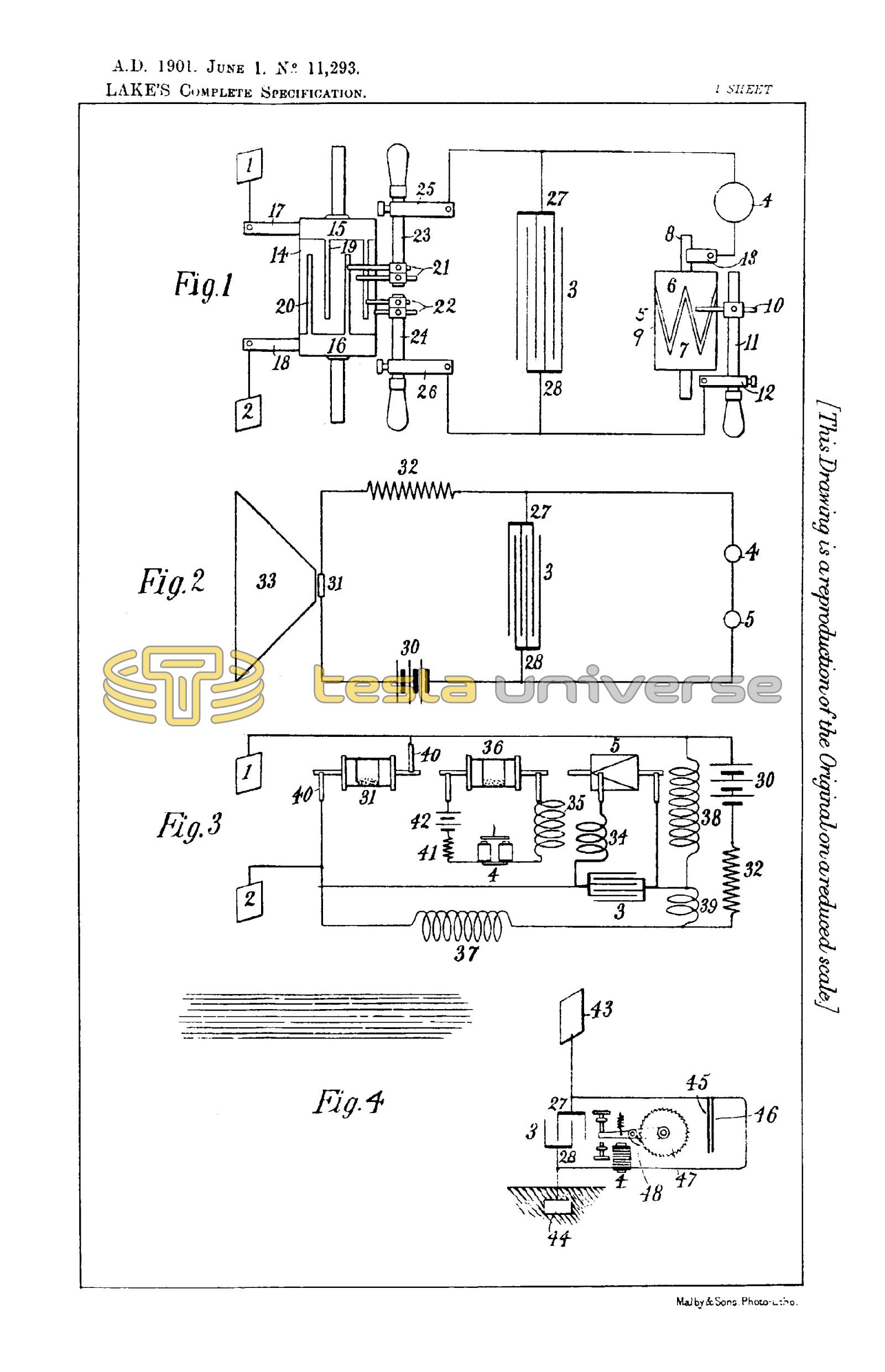
The general principles underlying the invention and the construction and mode of operation of the devices which are or which may be used in carrying out the invention, will be understood by reference to the accompanying drawing, in which
Figure 1 is a diagrammatic illustration of the apparatus employed when the energy from the transmitting source is to be stored.
Figure 2 is a diagrammatic illustration of the apparatus employed when the stored energy is obtained from an independent source and merely controlled by the effects transmitted.
Figure 3 is a diagram of a modified arrangement of apparatus for the same purpose, and
Figure 4 is a similar illustration of an apparatus for simultaneously charging a condenser by means of rays or radiations and an independent source of electrical energy, and discharging it through a receiver.
Referring now to Figure 1: At any two points in the transmitting medium between which there exists or may be obtained in any manner, through the action of the disturbances or effects to be utilized or investigated, a difference of electrical potential of any magnitude, I arrange two plates or electrodes 1 2 so that they may be oppositely charged through the agency of such effects or disturbances, and I connect these electrodes to the terminals of a highly insulated condenser 3, generally of considerable capacity. To the condenser terminals there is also connected the receiver 4, in series with a device of suitable construction which performs the function of periodically discharging the condenser through the receiver at and during such intervals of time as may be best suitable for the purpose contemplated. This device may consist merely of two stationary electrodes separated by a feeble dielectric layer of minute thickness, or it may comprise terminials, one or more of which are movable, and actuated by any suitable force, so as to be brought into and out of contact with each other in any convenient manner.
The special device shown for this purpose consists of a cylinder 5, made partly of conducting and partly of insulating material 6 and 7, respectively, which is rotated at the desired rate of speed by any suitable means. The conducting part 6 is in good electrical connection with the shaft 8, and is provided with tapering segments 9, upon which slides a brush 10 supported on a conducting rod 11 capable of longitudinal adjustment in a metallic support 12. Another brush 13 is arranged to bear upon the shaft 8, and it will be seen that wherever one of the segments 9 comes in contact with the brush 10 the circuit, including the receiver 4, is completed and the condenser discharged through the same. By an adjustment of the speed of rotation of the cylinder 5 and a displacement of the brush 10 along the cylinder, the circuit may be made to open and close in as rapid succession, and to remain open or closed during such intervals of time, as may be desired.
It will be readily seen that if the disturbances, of whatever nature they may be, cause definite amounts of electricity, of the same sign, to be conveyed in each of the plates or electrodes 1 and 2, ie definite amounts of positive electricity to one & of negative to the other either continuously or at intervals of time which are sufficiently long, the condenser will be charged to a certain potential, and, an adequate amount of energy being thus stored during the time determined by the discharging device, the receiver will be periodically operated by the electrical energy so accumulated.
But very often the character of the impulses and the conditions of their use are such that, without further provision, not enough potential energy would be accumulated in the condenser to operate the receiving device. This is the case when, for example, each of the plates or terminals 1 2 receives quantities of electricity of rapidly changing sign, or even when each receives quantities of electricity of the same sign, but only during periods which are short as compared with the intervals separating them. In such instances, the use of a special device is resorted to, which device is inserted in circuit between the plates 1 2 and the condenser 3, for the purpose of conveying to each of the terminals of the latter electrical charges of the proper quality and order of succession to enable the required amount of potential energy to be stored in the condenser.
One form of such device, which will serve for purposes of illustration of this feature of the invention, consists of a cylinder 14 of insulating material which is moved at a uniform rate of speed by clock-work or other suitable motive power, and is provided with two metal rings 15 16, upon which bear brushes 17 and 18, respectively, and which are connected in the manner shown to the two terminal plates 1 and 2. From the rings 15 16 extend narrow metallic segments 19 and 20, which, by the rotation of the cylinder 14 are brought alternately into contact with double brushes 21 and 22, carried by and in contact with conducting holders 23 and 24, which are adjustable longitudinally in the metallic supports 25 and 26 as shown. The latter are connected to the terminals 27 and 28 of the condenser 3, and it should be understood that they are capable of angular displacement as ordinary brush supports. The object of using two brushes in each of the holders is to vary at will the duration of the electric contact of the plates 1 and 2 with the terminals of the condensers.
The plates 1 and 2, through which the electrifications are conveyed to the brushes 17 and 18, may be at a considerable distance from each other, and both in the ground or both in the air, or one in the ground and the other in the air, preferably at some height, or they may be connected to conductors extending to some distance, or to the terminals of any kind of apparatus supplying electrical energy which is obtained from the energy of the impulses or disturbances transmitted from a distance through the natural media.
In illustration of the operation of the devices described, let it be assumed that alternating electrical impulses from a distant generator, are transmitted through the earth, and that it is desired to utilize these impulses in accordance with the present invention. This may be the case, for example, when such a generator is used for purposes of signalling in one of the ways above stated, as by having its terminals connected to two points of the earth distant from each other. In this case the plates 1 2 are first connected to two properly selected points of the earth ; the speed of rotation of the cylinder 14 is varied until it is made to turn in synchronism with the alternate impulses of the generator, and finally, the position of the brushes 21 and 22 is adjusted so that they are in contact with the segments 19 and 20 during the periods when the impulses are at or near the maximum of their intensity.
Only ordinary electrical skill and knowledge are required to make these adjustments, and a number of devices for effecting synchronous movement being well known, a detailed description of such devices is not considered necessary. The above requirements being fulfilled, electrical charges of the same sign will be conveyed to each of the condenser terminals as the cylinder 14 is rotated, and with each fresh impulse the condenser will be charged to a higher potential. The speed of rotation of the cylinder 5 being adjustable at will, the energy of any number of separate impulses may thus be accumulated in potential form and discharged through the receiver 4 upon the brush 10 coming in contact with one of the segments 9. It will be of course understood that the capacity of the condenser should be such as to allow the storing of a much greater amount of energy than is required for the ordinary operation of the receiver. Since by this method a relatively great amount of energy and in a suitable form may be made available for the operation of a receiver, the latter need not be very sensitive, but of course, when the impulses are very feeble, as when coming from a great distance, or when it is desired to operate a receiver very rapidly, then any of the well known devices capable of responding to very feeble influence may be used in this connection.
If instead of alternating impulses short impulses of the same direction are conveyed to the plates 1 and 2, the apparatus described may still readily be used, and for this purpose it is merely necessary to shift the brushes 21 and 22 while maintaining the same condition with regard to synchronism as before, so that the succeeding impulses will be permitted to pass into the condenser, but prevented from returning to the ground or transmitting medium during the intervals between them, owing to the interruption during such intervals of the connections leading from the condenser terminals to the plates.
Another way of using the apparatus with impulses of the same direction is to take off one pair of brushes, as 21, disconnect the plate 1 from the brush 17 and join it directly to the terminal 27 of the condenser, and to connect brush 17 with brush 18. Operated in this manner, and assuming the speed of rotation of cylinder 14 to be the same, the apparatus will now be adapted for a number of impulses per unit of time twice as great as in the preceding case. In all cases it is evidently important to adjust the duration of contact of segments 19 and 20 with brushes 21 and 22 in the manner indicated.
When the method and apparatus described are used for the purpose of transmitting signals or intelligence, the transmitter, it will be understood, is operated in such a way as to produce disturbances or effects which are varied or intermitted in some arbitrary manner, for example, to produce longer and shorter successions of impulses corresponding to the dashes and dots of a telegraph code, and the receiving device will respond to, and indicate, these variations or intermittances, since the storage device will be charged and discharged a number of times corresponding to the duration of the successions of impulses received.
In the form of apparatus for utilizing the stored energy of an independent source, and which is illustrated in Figures 2 and 3, a charging circuit is connected to the terminals 27 and 28 of the condenser 3, and includes a battery 30, a sensitive device 31, and a resistance 32, all connected in series, as shown. The battery should be of very constant electromotive force and of an intensity carefully determined to secure the best results. The resistance 32, which may be a frictional or an inductive one, is not absolutely necessary, but it is of advantage to use it in order to facilitate adjustment, and for this purpose it may be made variable in any convenient manner.
If the disturbances which are to be utilized or investigated are rays identical with or resembling those of ordinary light, the sensitive device 31 may be a selenium cell properly prepared so as to be highly susceptible to the influence of the rays, the action of which should be intensified by the use of a reflector 33. It is well known that when cells of this kind are exposed to such rays of greatly varying intensity, they undergo corresponding modifications of their electrical resistance, but in the ways they have heretofore been used they have been of very limited utility.
In addition to the circuit including the sensitive device or cell, 3l, another circuit is provided which is likewise connected to the terminals 27 and 28 of the condenser. This circuit is the same as that described in connection with Figure 1 and contains a receiver 4 and a device 5 for periodically discharging the condenser through the receiver.
It will be noted that, as shown in Figure 2, the receiving circuit is in permanent connection with the battery and condenser terminal 27, but it is sometimes desirable to entirely insulate the receiving circuit at all times, except at the moments when the device 5 operates to discharge the condenser, thus preventing any disturbing influences which might otherwise be caused in this circuit by the battery or the condenser during the period when the receiver should not be acted upon. In such a case two devices as 5 may be used, one in each connection from the condenser to the receiving circuit, or else one single device of this kind, but of suitably modified construction, so that it will make and break simultaneously and at proper intervals, both connections.
From the foregoing the operation of the apparatus will be understood. Normally, that is, when not influenced by the rays, or very slightly so, the cell 31, being of comparatively high resistance, permits only a relatively feeble current to pass from the battery into the condenser, and hence the latter is charged at too slow a rate to accumulate, during the time interval between two succeeding operations of the device 5, sufficient energy to operate the receiver. This condition is readily secured by a proper selection and adjustment of the various devices described, so that the receiver will remain unresponsive to the feeble discharges of the condenser which may take place when the cell 31 is acted upon but slightly, or not at all, by the rays or disturbances. But if now new rays are permitted to fall upon the cell, or if the intensity of those already acting upon it be increased by any cause, then its resistance will be diminished and the condenser will be charged by the battery at a more rapid rate, enabling sufficient potential energy to be stored in the condenser during the period of inaction of the device 5, to operate the receiver or to bring about any desired change in the receiving circuit when the device 5 acts. If the rays acting upon the cell or sensitive device 31 are varied or intermitted in any arbitrary manner, as when transmitting intelligence in the usual way from a distant station by means of short and long signals, the apparatus may readily be made to record, or to enable an operator to read the message, since the receiver, supposing it to be an ordinary electro-magnetic relay, for example, will be operated by each signal from the sending station a certain number of times having some relation to the duration of each signal. It will be readily seen, however, that if the rays are varied in any other way, as by impressing upon them changes in intensity, the succeeding condenser discharges will undergo corresponding changes in intensity which may be indicated or recorded by a suitable receiver, and distinguished irrespective of duration.
The electrical connections of the various devices illustrated may be made in various ways. For instance, the sensitive device, instead of being in series with, as shown, may be a shunt to the condenser, and in this case the condenser will store less energy when the sensitive device is energized by the rays and its resistance thereby diminished. The adjustment of the various instruments will then be such that the receiver will be operated only when the rays are diminished in intensity, or interrupted and entirely prevented from falling upon the sensitive cell.
The sensitive device may also be placed in shunt to the resistance 32, as well as to the condenser, or the several instruments may be connected in the manner of a Wheatstone bridge, as hereinafter described, but in each case the sensitive device operates to control the energy stored and utilized in some suitable way for actuating the receiver. The condenser may be replaced by other means of storage without departure from the invention.
In Figure 3 I have shown a more complete arrangement of the apparatus, particularly adapted for the investigation or utilization of very feeble impulses or disturbances, such as may be used in conveying signals or producing other desired effects at great distances. In this case the energy stored in the condenser 3 is passed through the primary 34 of a transformer, the secondary 35 of which is in a circuit containing the receiver 4. In order to render the apparatus still more suitable for use in detecting feeble impulses, in addition to the sensitive device 31 which is acted upon by the transmitted impulses, another such device 36 is included in the secondary circuit of the transformer.
The plan of connections is, in the main, that of a Wheatstone bridge, the four branches of which are formed of the sensitive device 31 and resistances 37, 38 and 39, all of which should be preferably inductive and adjustable in a continuous manner. The condenser is connected to two opposite points of the bridge, while a battery 30, in series with a continuously adjustable non-inductive resistance 32, is connected to the other pair of opposite points as usual. The four resistances 31, 37, 38 and 39 are so proportioned that under normal conditions, or when the device 31 is not influenced at all, or only slightly by the disturbances, there will be no difference of potential or, in any case the minimum of the same, at the terminals 27 and 28 of the condenser.
It is assumed in the present instance that the disturbances are such as will produce a difference of electrical potential, however small, between two points in the earth or air and, in order to apply this potential difference effectively the terminals of the sensitive device are as in Figure 1, two plates, 1 and 2, located at a suitable distance apart. Any form of sensitive device may be employed, that shown being one of familiar construction and consisting of an insulating tube having its ends closed by two conducting plugs with extensions upon which bear brushes 40, through which currents are conveyed to the device. The tubular space between the plugs is partially filled with a conducting sensitive powder. This tube is to be rotated by suitable clock work or otherwise at a uniform rate of speed, under which conditions it behaves towards disturbances of the kind now under consideration in a manner similar to that of a stationary cell of selenium towards rays of light. Its electrical resistance is diminished when it is acted upon by the disturbances and is automatically restored upon cessation of their influence.
The primary 34 is usually of few turns and low resistance, and is in circuit with a discharger 5 of the kind hereinbefore described.
The secondary coil 35 is usually of much finer wire and of many more turns. In circuit therewith is the receiver 4, shown as an ordinary relay; a continuously adjustable non-inductive resistance 41, a battery 42, of a properly determined and very constant electro-motive force and the sensitive device 36 of the same construction as that above described.
The electro-motive force of the battery 42 is so graduated by means of the adjustable resistance 41 that the dielectric layers in the sensitive device 36 are strained very nearly to the point of breaking down, and give way upon a slight increase of the electrical pressure on the terminals of the device. It will of course be understood that other means than the resistances 32 and 41 may be employed for securing the proper adjustment of the apparatus.
The various instruments being connected and adjusted in the manner described, the periodical closing of the primary circuit of the transformer by means of the device 5 will have no appreciable effect so long as the sensitive device 31 remains unaffected. But when, owing to the disturbances or impulses propagated through the media from a distant source, an additional electro-motive force, however small, is created between the terminals of the device 31, the dielectric layers give way and allow the current of the battery 30 to pass through, thus causing a difference of potential at the terminals 27, 28 of the condenser 3. A sufficient amount of energy being now stored in this instrument during the time interval between each two succeeding operations of the device 5, each closure of the primary circuit by the latter results in the passage of a sudden current impulse through the coil 34, which induces a corresponding current of relatively high electro-motive force in the secondary coil 35. This breaks down the resistance of the sensitive device 36 and allows the current of battery 42 to pass and to operate the receiver 4, but only for a moment, since by the rotation of the devices 5, 31 and 36, which may all be driven from the same shaft, the original conditions are restored, assuming, of course, that the electro-motive force set up by the disturbances at the terminals of the sensitive device 31 is only momentary, or of a duration not longer than the time of closure of the primary circuit; otherwise the receiver will be actuated a number of times, and so long as the influence of the disturbances upon the device 31 continues.
In order to render the discharged energy of the condenser more effective in causing the operation of the receiver, the resistance of the primary circuit should be very small and the secondary coil 35 should have a number of turns many times greater than that of the primary coil 34. It is preferable to make the inductive resistances 37 and 38 relatively large, as they are in a shunt to the device 31, and might, if made too small, impair its sensitiveness.
In Figure 4, which illustrates the third method or plan above referred to, 43, represents an insulated plate or conducting body which is to be exposed to the action of rays or radiations, and 44 another plate, the two being connected in series with the condenser 3. The terminals 27 and 28 of the latter are also connected to a circuit containing a receiver 4, and a circuit controlling device which, in this case, is composed of two very thin conducting plates 45, 46, placed in close proximity and very mobile, either by reason of extreme flexibility or owing to the character of their support. To improve their action they should be enclosed in a receptacle, from which the air may be exhausted. The receiver 4 is shown as consisting of an electro-magnet and armature, a retractile spring and a ratchet wheel 47, provided with a spring pawl 48, which is pivoted to the armature as shown. The terminal 44 may be connected to one of the poles of a battery or other source of electricity, or it may itself be, or be connected with any conducting body or object of such properties, or so conditioned, that by its means electricity of the required sign will be supplied to the terminal.
A simple way of supplying positive or negative electricity to the terminal is to connect the same either to an insulated conductor supported at some height in the atmosphere, or to a grounded conductor, the former, as is well known furnishing positive, the latter negative electricity.
The apparatus being arranged as shown, it will be found that when the radiations of the sun or of any other source capable of producing the effects described, fall upon the plate 43 an accumulation of energy in the condenser 3 will result. This phenomenon, I believe, is best explained as follows: The sun, as well as other sources of radiant energy, throws off minute particles of matter positively electrified, which, impinging upon the plate 43, communicate an electrical charge to the same. The opposite terminal of the condenser being connected to the ground, which may be considered as a vast reservoir of negative electricity, a feeble current flows continuously into the condenser and, inasmuch as these supposed particles are of an inconceivably small radius or curvature and consequently charged to a relatively very high potential, this charging of the condenser may continue, as I have found in practice, almost indefinitely, even to the point of rupturing the dielectric. Obviously, whatever circuit controller be employed, it should operate to close the circuit, in which it is included when the potential in the condenser has reached the desired magnitude.
By carefully observing well known rules of design and adjustment of the instruments, the several forms of apparatus above described may be made extremely sensitive and capable of responding to the faintest influences, thus making it possible to utilize impulses or disturbances transmitted from very great distances and too feeble to be detected or utilized in any of the ways heretofore known, and on this account the invention lends itself to many scientific and practical uses of great value.
It is evident that, since one of the chief requirements which the invention herein described is designed to meet is the detection and utilization of feeble transmitted effects, many of the improvements which have been illustrated are also applicable to ordinary telegraphic and telephonic systems involving the use of artificial lines, and such applications I regard as within the scope of my invention and claims.
Having now particularly described and ascertained the nature of my said invention and in what manner the same is to be performed, as communicated to me by my foreign correspondent, I declare that what I claim is: -
- The method of utilizing effects or disturbances transmitted from a distance through the natural media, which consists in storing the energy derived from such effects or controlling thereby the storage of energy from an independent source, and using the accumulated energy so obtained to operate a receiving device.
- The method of utilizing effects or disturbances transmitted from a distance through the natural media, which consists in charging therewith or controlling thereby the charging of a condenser and discharging the accumulated energy through a receiving device.
- The method of utilizing effects or disturbances transmitted from a distance through the natural media, which consists in charging therewith or effecting thereby the charging of a condenser during any desired time intervals, and discharging the accumulated energy for periods of time predetermined as to succession and duration, through a receiving device.
- The method herein described of producing arbitrarily varied or intermitted electrical disturbances or effects, transmitting such disturbances or effects through the natural media to a distant receiving station, establishing thereby a flow of electrical energy in a circuit at such station, charging a condenser with electrical energy from such circuit and discharging the accumulated potential energy so obtained into or through a receiving device at arbitrarily predetermined intervals of time.
- The method herein described of producing arbitrarily varied or intermitted electrical disturbances or effects, transmitting such disturbances or effects through the natural media to a distant receiving station, establishing thereby a flow of energy in a circuit at such station, selecting and directing the impulses in said circuit so as to render them suitable for charging a condenser, charging a condenser with the impulses so selected or directed and discharging the accumulated potential energy so obtained into or through a receiving device.
- The method and apparatus described herein and illustrated in Figure 4, by which a condenser is simultaneously charged by rays or radiations and an independent means and discharged through a suitable receiver, either automatically by the accumulated energy or by other means, suitably controlled.
- The apparatus herein described and illustrated in Figure 1, for receiving and selecting when necessary electrical impulses transmitted through the natural media from a distant source, charging a condenser and discharging the same through a receiver, as set forth.
- The apparatus herein described and illustrated in Figures 2 and 3, for controlling the charging of a condenser from an independent source, by means of effects or disturbances transmitted from a distance through the natural media, and discharging the same through a condenser.
Dated this 1st day of June 1901.
HASELTINE LAKE & Co.
45, Southampton Buildings, London, W.C., Agents for the Applicant.