Nikola Tesla Patents
Nikola Tesla British Patent 186,082 - Improvements in the Construction of Steam and Gas Turbines
PATENT SPECIFICATION
186,082
Application Date: Mar. 24, 1921. No. 9097/21.
Complete Left: Sept. 2, 1921.
Complete Accepted: Sept. 25, 1922.
PROVISIONAL SPECIFICATION.
Improvements in the Construction of Steam and Gas Turbines
I, Nikola Tesla, Mechanical and Electrical Engineer, citizen of the United States of America, of 8, West 40th Street, New York City, U.S.A., do hereby declare the nature of this invention to be as follows:-
In a British Patent, Number 24,001 of 1910, I have described a bladeless turbine having a rotor consisting of discs with openings in the central portions and separating star-washers, these parts when assembled being riveted together into a single solid structure and keyed to the shaft. This form of rotor operates satisfactorily but in long experience certain improvements in its construction have been found desirable and these constitute my present invention.
In the new design I employ two heavier end-plates which are machined tapering toward the periphery for the purpose of reducing the maximum centrifugal stress as much as practicable. The inside discs, of relatively thin material, are rolled, forged or ground tapering in like manner and with the same object in view, but this may not always be necessary and plates, made of sheet metal of substantially uniform thickness as furnished by the mills, can be employed. Each of the thick as well as thin plates is provided with exhaust openings, leaving a solid central portion like the hub and spokes of a wheel. Star-washers of similar configuration serve the purpose of keeping the discs apart in the center and for the peripheral spacing the thin plates have small holes drilled in them on a circle, or circles, of suitable diameter, and in these are driven tight-fitting studs which are upset at both ends by a special tool so that they will project beyond the metal on each side a trifle more than the thickness of the star-washers. When the plates are put together the separating studs do not come in line but are straddled in order to give opportunity for slight yielding, thereby eliminating constructional difficulties which might be caused by unevenness or other mechanical imperfections. Thus the rotor can be finished closely to predetermined overall dimensions and will run true on the outside even if the thin inside plates should vary a little in thickness or be slightly warped. To simplify this arrangement I provide only every second plate with studs, using plain ones between. Furthermore, with the object of cheapening the manufacture I dispense altogether with the former, accomplishing the spacing by means of small bosses or protuberances which are raised in the plates by blows or pressure and provide a die, practically reducing all the machine work on a thin plate to a single operation in a stamping press. The star-washers, while preferable, are not indispensable and may be replaced by round separating washers of a diameter about equal to that of the hub part of the discs.
All the plates and washers are fitted on and keyed to a sleeve threaded at the ends and equipped with nuts and collars for drawing the thick end-plates together or, if desired, the collars may be simply forced onto it and the ends upset. The sleeve has a hole fitting snugly on the shaft and is fastened to the same as usual.
This construction permits free expansion and contraction of each plate individually under the varying influence of heat and centrifugal force and possesses a number of other advantages which are of considerable practical moment. A larger active plate area and consequently more power is obtained for a given width, this improving efficiency. Warping is virtually eliminated and smaller side clearances may be used which results in diminished leakage and friction losses. The rotor is better adapted for dynamic balancing and through rubbing friction resists disturbing influences thereby insuring quieter running. For this reason and also because the discs are not rigidly joined it is safer against damage which might otherwise be caused by vibration or excessive speed.
Dated this 24th day of March, 1921.
Nikola Tesla.
COMPLETE SPECIFICATION.
Improvements in the Construction of Steam and Gas Turbines
I, Nikola Tesla, Electrical and Mechanical Engineer, citizen of the United States of America, of No. 8, West 40th Street, New York, N.Y., U.S.A., do hereby declare the nature of this invention and in what manner the same is to be performed, to be particularly described and ascertained in and by the following statement: -
In a British Patent, No. 24,001 of 1910, I have described a bladeless turbine having a rotor consisting of discs with openings in the central portions, and separating star-washers, these parts when assembled being riveted together into a single solid structure and keyed to the shaft. This form of rotor operates satisfactorily but in long experience certain improvements in its construction have been found desirable and these constitute my present invention.
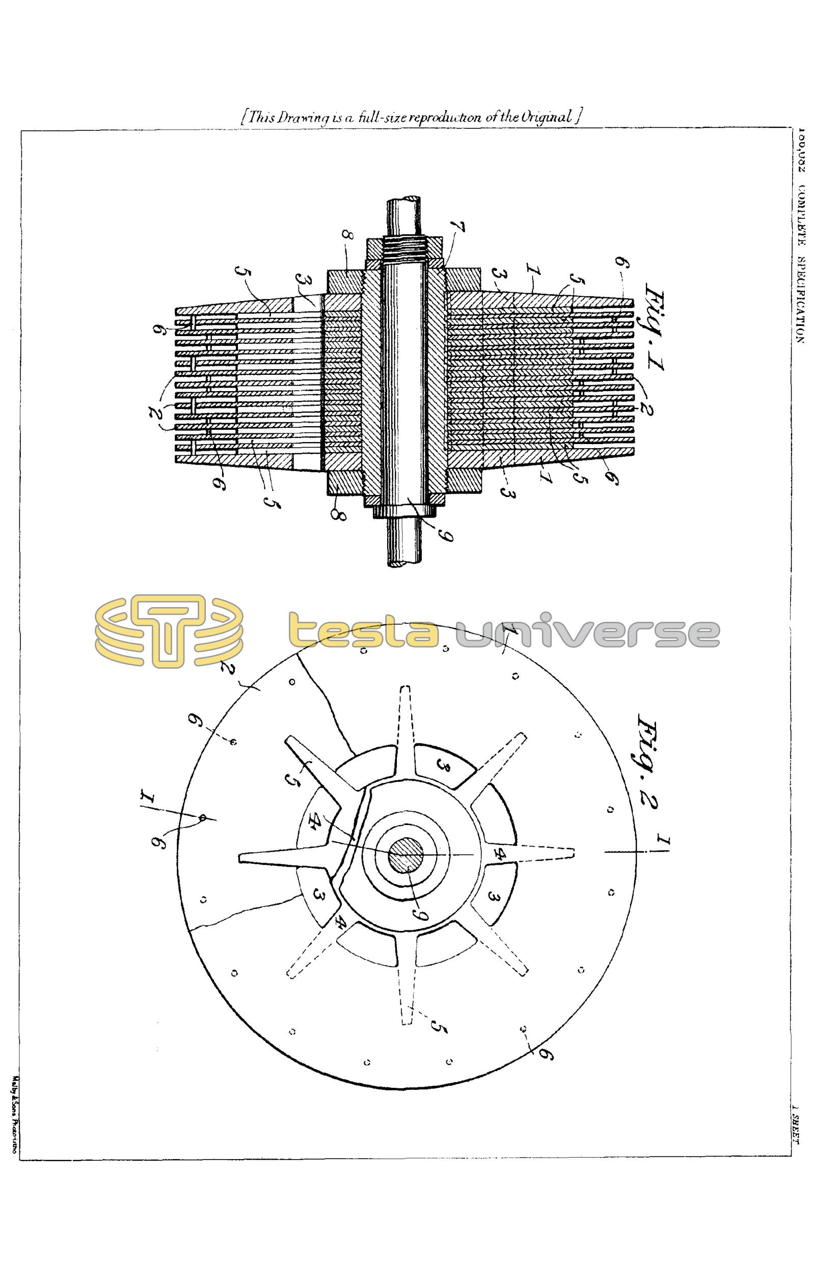
In the new design, illustrated in the accompanying drawings Fig. 1 and Fig. 2, respectively showing a section through the rotor on line II and a side view partly broken away exposing a portion of a star-washer, I preferably employ two heavier end-plates 1, 1 of suitable material made tapering on the outside toward the periphery, as shown, for the purpose of reducing the maximum centrifugal stress as much as practicable. The inside discs 2, 2 .... are relatively thin and may be tapered on both sides in the peripheral part beyond the star-washers with the same object in view, but plates of substantially uniform thickness, as furnished by the mills, can also be employed. Each of the plates - thick as well as thin - is provided with exhaust openings 3, 3 .... leaving a solid central portion 4, 4 .... like the hub and spokes of a wheel. If there is an odd number of thin plates the central one may be plain, if desired. Star-washers 5, 5 .... of similar configuration, and projecting with their arms considerably beyond the exhaust openings, serve the purpose of keeping the discs apart in the central region and for the peripheral spacing the thin plates have small holes drilled in them preferably on a circle, or circles, of suitable diameter, and in these are driven tight-fitting spacers or studs 6, 6 .... which may be upset at the ends so that they will project on each side a trifle more than the thickness of the star-washers 5, 5 .... When the plates are put together the separating studs do not come in line but are straddled, as indicated in Fig. 1 and in the broken away part of Fig. 2 by the plain and dotted small circles, in order to give opportunity for slight yielding, thereby eliminating constructional difficulties which might be caused by unevenness or other mechanical imperfections. Such a rotor can be finished closely to predetermined overall dimensions and will run true on the outside even if the thin inside plates should vary a little in thickness or be slightly warped. To simplify the construction I provide only every second plate with studs, using plain ones between. Furthermore, with the object of cheapening the manufacture, I may dispense with the studs altogether, accomplishing the peripheral spacing by means of other spacers such as small bosses or protuberances raised in the plates, thus reducing the machine work on the thin ones to a single operation in a stamping press. The star-washers, while preferable, are not indispensable and may be replaced by round separating washers of a diameter about equal to that of the hub part of the discs.
All the plates and washers are fitted on and keyed to a sleeve 7, threaded at the ends and equipped with nuts 8, 8 for drawing the thick end-plates together or, if desired, the nuts and threads on the sleeve may be omitted, collars forced on its ends and the same upset. The sleeve fits snugly on the shaft 9 and is fastened to it as usual.
This construction enables the use of thinner inside plates then practicable in the earlier form, thus affording a greater active surface and increasing correspondingly the output, while the smaller clearances are instrumental in reducing the leakage losses.
Having now particularly described and ascertained the nature of my said invention and in what manner the same is to be performed, I declare that what I claim is:-
- A rotor for steam and gas turbines composed of plane spaced discs and two rigid end-plates holding them in fixed position laterally but permitting their independent expansion or contraction in the radial direction, said discs and plates being provided with exhaust openings in their central portions, substantially as described.
- A turbine rotor comprising plane discs with spacers allowing radial displacement, central separating washers and two rigid tapering end-plates for holding the structure firmly near the shaft, said discs and end-plates having exhaust openings in their central portions, substantially as described.
- In a rotor for high-speed turbines plane spaced discs with exhaust openings in their central portions and tapering towards the periphery as, and for the purpose, described.
- A turbine rotor consisting of a system of discs held apart by spacers in frictional contact with them and alternately straddled as, and for the purpose, described.
- A turbine rotor composed of plane parallel discs having exhaust openings in their central portions and projections for holding them apart near the periphery, substantially as described.
- In a turbine rotor composed of flat discs with exhaust openings in their central portions, star washers of similar configuration and projecting with their arms considerably beyond the openings in the discs, substantially as described.
Dated the 23rd day of August, 1921.
Nikola Tesla.