Nikola Tesla Patents
Nikola Tesla U.S. Patent 1,119,732 - Apparatus for Transmitting Electrical Energy
NIKOLA TESLA, OF NEW YORK, N. Y.
TESLA PATENT 1,119,732 APPARATUS FOR TRANSMITTING ELECTRICAL ENERGY.
| 1,119,732. | Specification of Letters Patent. | Patented Dec. 1, 1914. |
Application filed January 18, 1902. Serial No. 90,245. Renewed May 4,1907. Serial No. 371,817.
To all whom it may concern:
Be it known that I, NIKOLA TESLA, a citizen of the United States, residing in the borough of Manhattan, in the city, county, and State of New York, have invented certain new and useful Improvements in Apparatus for Transmitting Electrical Energy, of which the following is a specification, reference being had to the drawings accompanying and forming a part of the same.
In endeavoring to adapt currents or discharges of very high tension to various valuable uses, as the distribution of energy through wires from central plants to distant places of consumption, or the transmission of powerful disturbances to great distances, through the natural or non-artificial media. I have encountered difficulties in confining considerable amounts of electricity to the conductors and preventing its leakage over their supports, or its escape into the ambient air, which always takes place when the electric surface density reaches a certain value.
The intensity of the effect of a transmitting circuit with a free or elevated terminal is proportionate to the quantity of electricity displaced, which is determined by the product of the capacity of the circuit, the pressure, and the frequency of the currents employed. To produce an electrical movement of the required magnitude it is desirable to charge the terminal as highly as possible, for while a great quantity of electricity may also be displaced by a large capacity charged to low pressure, there are disadvantages met with in many cases when the former is made too large. The chief of these are due to the fact that an increase of the capacity entails a lowering of the frequency of the impulses or discharges and a diminution of the energy of vibration. This will be understood when it is borne in mind, that a circuit with a large capacity behaves as a slackspring, whereas one with a small capacity acts like a stiff spring, vibrating more vigorously. Therefore, in order to attain the highest possible frequency, which for certain purposes is advantageous and, apart from that, to develop the greatest energy in such a transmitting circuit, I employ a terminal of relatively small capacity, which I charge to as high a pressure as practicable. To accomplish this result I have found it imperative to so construct the elevated conductor, that its outer surface, on which the electrical charge chiefly accumulates, has itself a large radius of curvature, or is composed of separate elements which, irrespective of their own radius of curvature, are arranged in close proximity to each other and so, that the outside ideal surface enveloping them is of a large radius. Evidently, the smaller the radius of curvature the greater, for a given electric displacement, will be the surface-density and, consequently, the lower the limiting pressure to which the terminal may be charged without electricity escaping into the air. Such a terminal I secure to an insulating support entering more or less into its interior, and I likewise connect the circuit to it inside or, generally, at points where the electric density is small. This plan of constructing and supporting a highly charged conductor I have found to be of great practical importance, and it may be usefully applied in many ways.
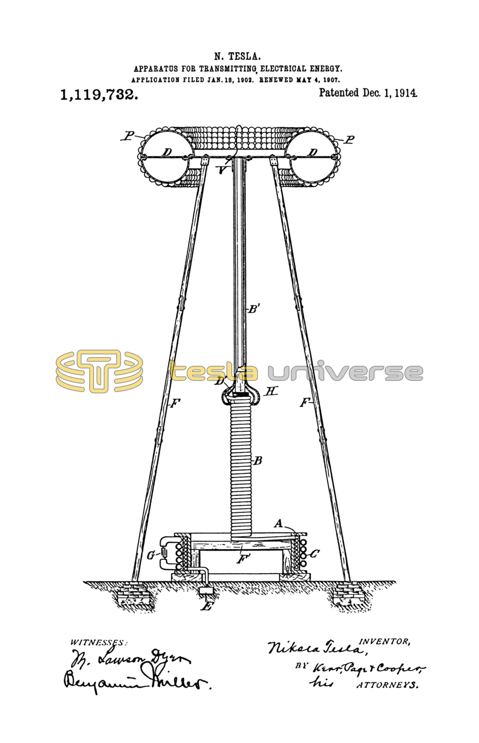
Referring to the accompanying drawing, the figure is a view in elevation and part section of an improved free terminal and circuit of large surface with supporting structure and generating apparatus.
The terminal D consists of a suitably shaped metallic frame, in this case a ring of nearly circular cross section, which is covered with half spherical metal plates P P, thus constituting a very large conducting surface, smooth on all places where the electric charge principally accumulates. The frame is carried by a strong platform expressly provided for safety appliances, instruments of observation, etc., which in turn rests on insulating supports F F. These should penetrate far into the hollow space formed by the terminal, and if the electric density at the points where they are bolted to the frame is still considerable, they may be specially protected by conducting hoods as H.
A part of the improvements which form the subject of this specification, the transmitting circuit, in its general features, is identical with that described and claimed in my original Patents Nos. 645,576 and 649,621. The circuit comprises a coil A which is in close inductive relation with a primary C, and one end of which is connected to a ground-plate E, while its other end is led through a separate self-induction coil B and a metallic cylinder B' to the terminal D. The connection to the latter should always be made at, or near the center, in order to secure a symmetrical distribution of the current, as otherwise, when the frequency is very high and the flow of large volume, the performance of the apparatus might be impaired. The primary C may be excited in any desired manner, from a suitable source of currents G, which may be an alternator or condenser, the important requirement being that the resonant condition is established, that is to say, that the terminal D is charged to the maximum pressure developed in the circuit, as I have specified in my original patents before referred to. The adjustments should be made with particular care when the transmitter is one of great power, not only on account of economy, but also in order to avoid danger. I have shown that it is practicable to produce in a resonating circuit as E A B B' D immense electrical activities, measured by tens and even hundreds of thousands of horse-power, and in such a case, if the points of maximum pressure should be shifted below the terminal D, along coil B, a ball of fire might break out and destroy the support F or anything else in the way. For the better appreciation of the nature of this danger it should be stated, that the destructive action may take place with inconceivable violence. This will cease to be surprising when it is borne in mind, that the entire energy accumulated in the excited circuit, instead of requiring, as under normal working conditions, one quarter of the period or more for its transformation from static to kinetic form, may spend itself in an incomparably smaller interval of time, at a rate of many millions of horse power. The accident is apt to occur when, the transmitting circuit being strongly excited, the impressed oscillations upon it are caused, in any manner more or less sudden, to be more rapid than the free oscillations. It is therefore advisable to begin the adjustments with feeble and somewhat slower impressed oscillations, strengthening and quickening them gradually, until the apparatus has been brought under perfect control. To increase the safety, I provide on a convenient place, preferably on terminal D, one or more elements or plates either of somewhat smaller radius of curvature or protruding more or less beyond the others (in which case they may be of larger radius of curvature) so that, should the pressure rise to a value, beyond which it is not desired to go, the powerful discharge may dart out there and lose itself harmlessly in the air. Such a plate, performing a function similar to that of a safety valve on a high pressure reservoir, is indicated at V.
Still further extending the principles underling my invention, special reference is made to coil B and conductor B'. The latter is in the form of a cylinder with smooth or polished surface of a radius much larger than that of the half spherical elements P P, and widens out at the bottom into a hood H, which should be slotted to avoid loss by eddy currents and the purpose of which will be clear from the foregoing. The coil B is wound on a frame or drum D1 of insulating material, with its turns close together. I have discovered that when so wound the effect of the small radius of curvature of the wire itself is overcome and the coil behaves as a conductor of large radius of curvature, corresponding to that of the drum. This feature is of considerable practical importance and is applicable not only in this special instance, but generally. For example, such plates at P P of terminal D, though preferably of large radius of curvature, need not be necessarily so, for provided only that the individual plates or elements of a high potential conductor or terminal are arranged in proximity to each other and with their outer boundaries along an ideal symmetrical enveloping surface of a large radius of curvature, the advantages of the invention will be more or less fully realized. The lower end of the coil B—which, if desired, may be extended up to the terminal D—should be somewhat below the uppermost turn of coil A. This, I find, lessens the tendency of the charge to break out from the wire connecting both and to pass along the support F'.
Having described my invention, I claim:
1. As a means for producing great electrical activities a resonant circuit having its outer conducting boundaries, which are charged to a high potential, arranged in surfaces of large radii of curvature so as to prevent leakage of the oscillating charge, substantially as set forth.
2. In apparatus for the transmission of electrical energy a circuit connected to ground and to an elevated terminal and having its outer conducting boundaries, which are subject to high tension, arranged in surfaces of large radii of curvature substantially as, and for the purpose described.
3. In a plant for the transmission of electrical energy without wires, in combination with a primary or exciting circuit a secondary connected to ground and to an elevated terminal and having its outer conducting boundaries, which are charged to a high potential, arranged in surfaces of large radii of curvature for the purpose of preventing leakage and loss of energy, substantially as set forth.
4. As a means for transmitting electrical energy to a distance through the natural media a grounded resonant circuit, comprising a part upon which oscillations are impressed and another for raising the tension, having its outer conducting boundaries on which a high tension charge accumulates arranged in surfaces of large radii of curvature, substantially as described.
5. The means for producing excessive electric potentials consisting of a primary exciting circuit and a resonant secondary having its outer conducting elements which are subject to high tension arranged in proximity to each other and in surfaces of large radii of curvature so as to prevent leakage of the charge and attendant lowering of potential, substantially as described.
6. A circuit comprising a part upon which oscillations are impressed and another part for raising the tension by resonance, the latter part being supported on places of low electric density and having its outermost conducting boundaries arranged in surfaces of large radii of curvature, as set forth.
7. In apparatus for the transmission of electrical energy without wires a grounded circuit the outer conducting elements of which have a great aggregate area and are arranged in surfaces of large radii of curvature so as to permit the storing of a high charge at a small electric density and prevent loss through leakage, substantially as described.
8. A wireless transmitter comprising in combination a source of oscillations as a condenser, a primary exciting circuit and a secondary grounded and elevated conductor the outer conducting boundaries of which are in proximity to each other and arranged in surfaces of large radii of curvature, substantially as described.
9. In apparatus for the transmission of electrical energy without wires an elevated conductor or antenna having its outer high potential conducting or capacity elements arranged in proximity to each other and in surfaces of large radii of curvature so as to overcome the effect of the small radius of curvature of the individual elements and leakage of the charge, as set forth.
10. A grounded resonant transmitting circuit having its outer conducting boundaries arranged in surfaces of large radii of curvature in combination with an elevated terminal of great surface supported at points of low electric density, substantially as described.
NIKOLA TESLA.
M. LAWSON DYER,
RICHARD DONOVAN.