Nikola Tesla Patents
Nikola Tesla U.S. Patent 613,735 - Electric Circuit Controller
NIKOLA TESLA, OF NEW YORK, N. Y.
ELECTRIC-CIRCUIT CONTROLLER.
SPECIFICATION forming part of Letters Patent No. 613,735, dated November 8, 1898.
Application filed April 19, 1898. Serial No. 678,127. (No model.)
To all whom it may concern:
Be it known that I, NIKOLA TESLA, residing at New York, in the county and State of New York, have invented certain new and useful Improvements in Electrical-Circuit Controllers, of which the following is a specification, reference being had to the drawings accompanying and forming a part of the same.
In the electrical system or combination of apparatus for the conversion of electrical energy by means of the discharges of a condenser invented and heretofore described by me the means employed for making and breaking the electric circuit, though performing a subordinate function, may from the peculiar conditions which exist become a highly important consideration, not only as regards their practicability and durability, but also the economy in the operation of the system or apparatus. Of such importance is this consideration that for the most efficient and reliable operation of my said system I have found it necessary to devise special appliances for making and breaking the circuit which differ materially in construction and mode of operation from any previously-existing devices of this character of which I am aware. In the forms of such apparatus which I have produced at least one of the terminals is a conducting fluid, while the other is usually a solid conductor or series of conductors, both being preferably enclosed in a gas-tight receptacle and brought by rotary movement into rapidly intermittent contact. I have shown and described typical forms of such circuit-controllers in applications Serial No. 660,518, filed December 2, 1897; Serial No. 639,227, filed June 3, 1897, and Serial No. 671,897, filed February 28, 1898.
The invention, subject of my present application, pertains to apparatus of this class and involves certain improvements in the construction and mode of operation of the same which have primarily for their object to secure a greater relative speed between the two terminals, whereby the periods of make-and-break, during which occurs the chief loss of energy, may be materially shortened and also a higher frequency of current impulses secured. A brief consideration of the forms of circuit controller of this general kind which I have heretofore shown and described will conduce to a better understanding of the principles followed in the construction of the apparatus upon which my present application is based and of the primary object which I have in view—to increase the relative speed of the two terminals in approaching and receding from each other.
In some forms of the circuit-controllers heretofore described by me I employ a closed receptacle capable of being maintained in rapid rotation. Within this receptacle is mounted a body the rotation of which is retarded or prevented and which carries a tube or duct which takes up a conducting fluid from the receptacle when the latter is rotated and directs the said fluid against a conductor or series of spaced conductors carried by the rotating receptacle. This apparatus, while effective to a high degree and possessing many advantages over previously-existing forms, is nevertheless subject to certain limitations as to efficiency, having regard to the speed at which the receptacle is rotated, for not only may an undue loss of energy result from rotating the receptacle, but also from the unnecessarily-rapid movement of the conducting fluid. With a view to improving the apparatus in these particulars I devised forms in which the receptacle was stationary and the interior terminal conductor rotated, and by this means I reduced the mass and weight of the moving parts. I also employed a device in the nature of a pump, which formed a part of the circuit-controller proper and was operated by the motor used for rotating the conductor, and thus maintained a flow of conducting fluid from ducts in the receptacle against the rotating conductor with no greater speed than required for efficient operation. By such an apparatus it is not only possible to secure a higher relative speed between the two terminals, but to do this with a smaller expenditure of mechanical energy. To still further increase the relative speed of the terminals, I now provide for rotating each of the terminals with respect to the other, so that the rate of mutual contacts is very greatly increased.
Obviously various means may be employed for rotating the conductors, or, in general, the two essential parts which by their movement produce a make and break; but in the annexed drawings I have only shown such forms of the apparatus as best illustrate the present improvement.
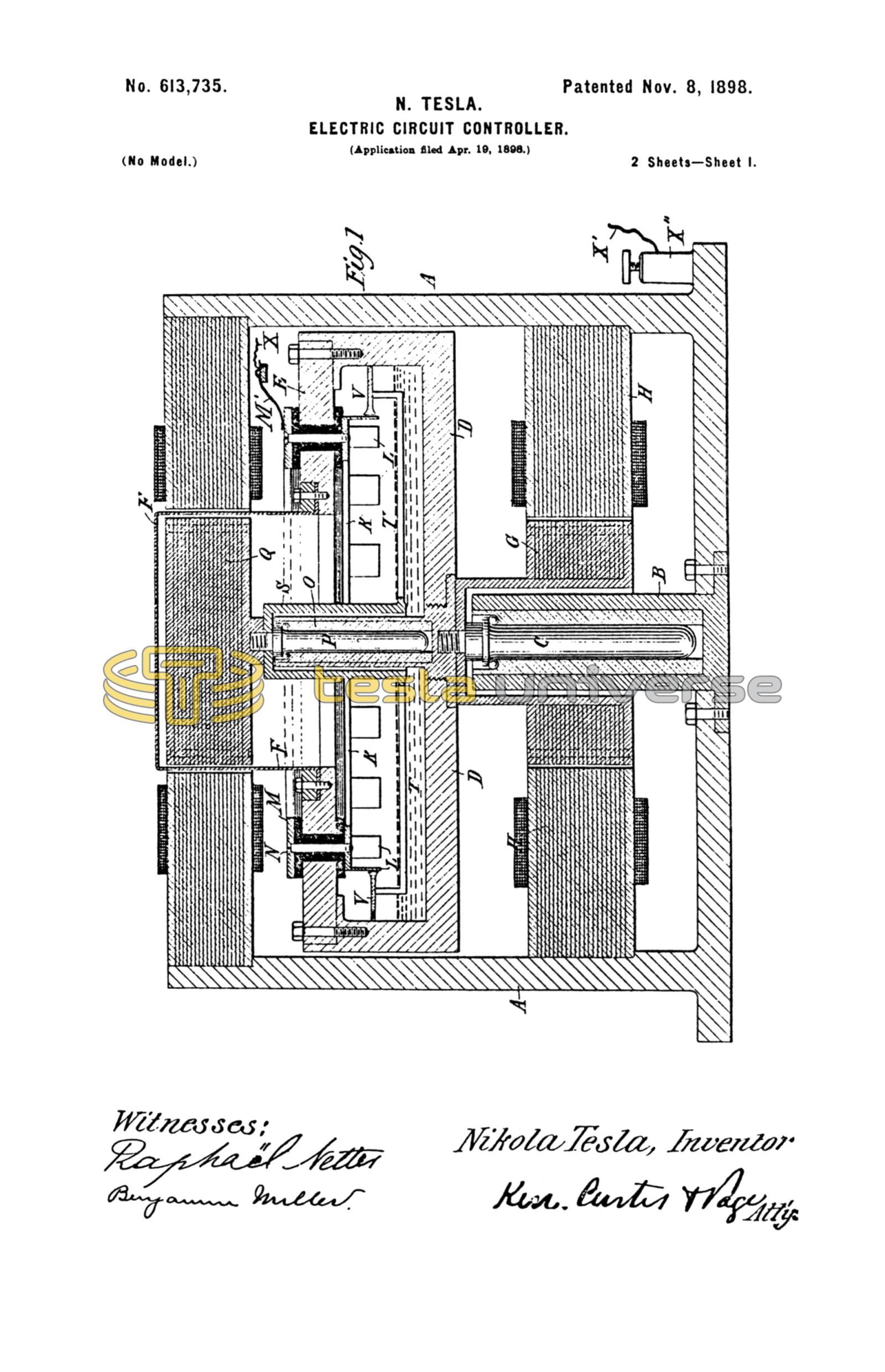
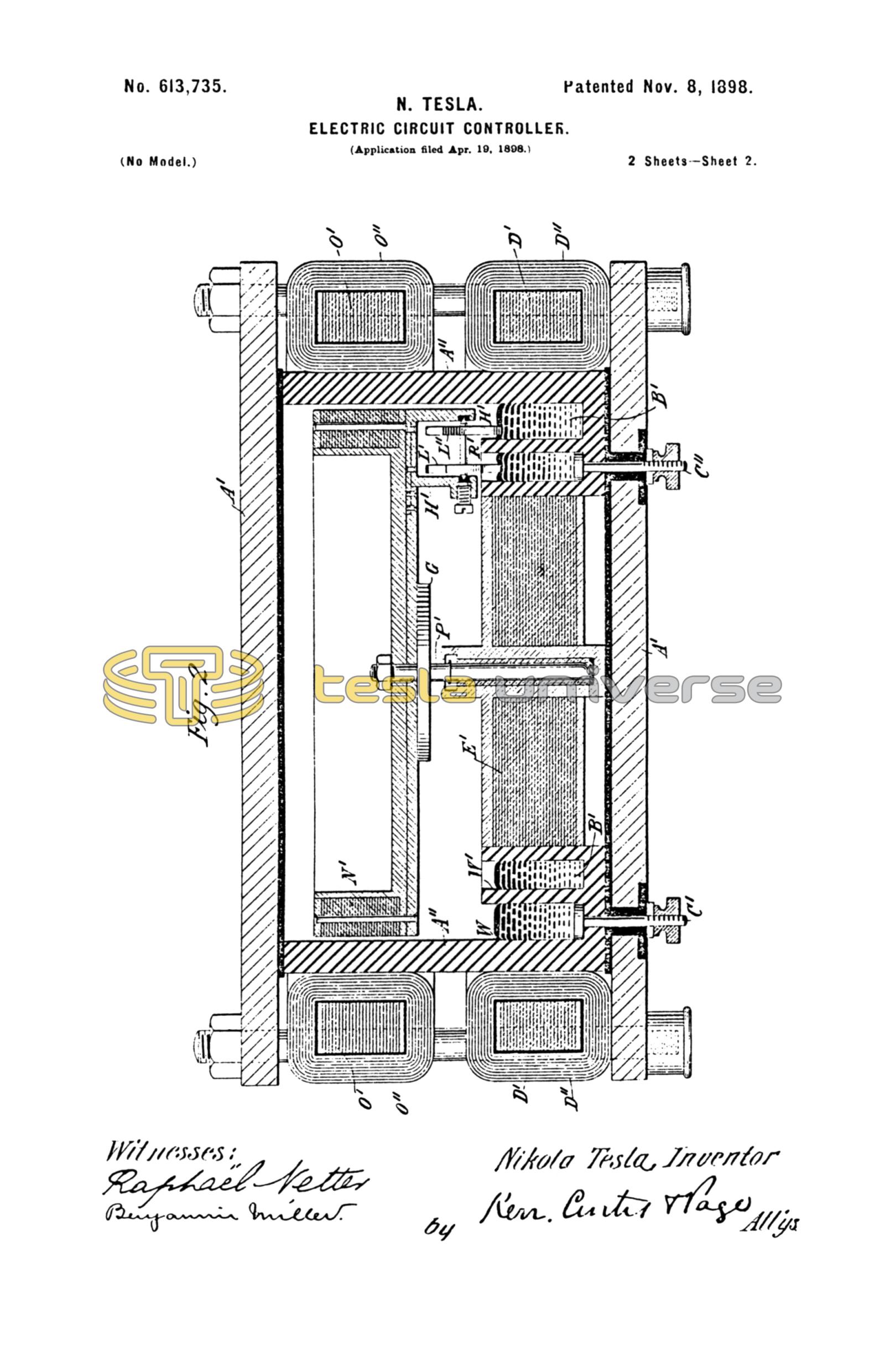
Figure 1 is a central vertical section of a circuit-controller comprising a conductor or series of conductors forming one terminal and means for maintaining a jet or jets of conducting fluid constituting the other terminal, which are arranged to be rotated in opposite directions. Fig. 2 is a similar view of a modified form of circuit-controller.
A designates a casting of cylindrical form within which is a standard or socket B, in which is mounted a vertical spindle C, carrying the circuit-controlling mechanism. The said mechanism is contained in a receptacle D, of iron or steel, the top or cover of which is composed of an annular plate E and a cap or dome F, the latter being of insulating material or of a metal of comparatively high specific resistance, such as German silver. The receptacle D as a whole in made air-tight and any suitable means may be employed to effect its rotation, the particular device shown for this purpose being an electromagnetic motor, one element, G, of which is secured to the spindle C or receptacle D and the other, H, to the box or case A. Within the receptacle D and secured to the top of the same, but insulated therefrom, is a circular conductor K, with downwardly-extending projections or teeth L. This conductor is maintained in electrical connection with a plate M outside of the receptacle by means of screws or bolts N, passing through insulated gaskets in the top of the receptacle D. Within the latter is a standard or socket O, in which is mounted as spindle P, concentric with the axis of the receptacle.
Any suitable means may be provided for rotating the spindle P independently of the receptacle D; but for this purpose I again employ an electromagnetic motor, one element, Q, of which is secured to the spindle P within the receptacle D and the other, R, is secured to the box A and surrounds the cap or dome F, within which is mounted the armature Q.
Depending from the spindle P or the armature Q is a cylinder S, to which are secured arms T T, extending radially therefrom and supporting short tubes or ducts V between the peripheral walls of the receptacle D and the series of teeth or projections L.
The tubes V have openings at one end in close proximity to the inner wall of the receptacle D and turned in a direction opposite to that in which the latter is designed to rotate and at the other end orifices which are adapted to direct a stream or jet of fluid against the projections L.
To operate the apparatus, the receptacle D, into which a suitable quantity of conducting fluid, such as mercury, is first poured, and the spindles P are both set in rotation by their respective motors and in opposite directions. By the rotation of receptacle D the conducting fluid is carried by centrifugal force up the sides or walls of the same and is taken up by the tubes or ducts V and discharged against the rotating conductors L. If, therefore, one terminal of the circuit be connected with any part of the receptacle D or the metal portions of the instrument in electrical connection therewith and the other terminal be connected to the plate M, the circuit between these terminals will be completed whenever a jet from one of the ducts V is discharged against one of the projections L and interrupted when the jets are discharged through the spaces between such projections. I have indicated the necessary circuit connections by wires X and X', connected, respectively, with a brush M', bearing upon the circular plate M, and a binding-post X'', set in the frame or casing A.
In Fig. 2 a modified form of apparatus is shown and by means of which similar results are obtained. In this device the top and bottom A' of the receptacle are metal plates, while the cylindrical portion or sides A'' is of insulating material, such as porcelain. Within the receptacle and preferably integral with the side walls A'' are two annular troughs W W', which contain a conducting fluid B', such as mercury. Terminals C' C'', passing through the bottom of the receptacle through insulating and packed sleeves, afford a means of connecting the mercury in the two troughs with the conductors of the circuit. Surrounding that portion of the device in which the troughs W W' lie is a core D', wound with coils D'', arranged in any suitable and well-known manner to produce, when energized by currents of different phase, a rotating magnetic field in the space occupied by the two bodies of mercury. To intensify the action, a circular laminated core E' is placed within the receptacle. If by this or any other means the mercury is set in motion and caused to flow around in the troughs, and if a conductor be mounted in position to be rotated by the mercury, and when so rotated to make intermittent contact therewith, a circuit-controller may be obtained of novel and distinctive character and capable of many useful applications independently of the other natures which are embodied in the complete device which is illustrated. For the present purpose I provide in the center of the receptacle a socket in which is mounted a spindle P', carrying a disk G'. Depending from said disk are arms H', which afford bearings for a shaft K', supporting two star-shaped wheels L' L'', arranged to make contact with the mercury in the two troughs, respectively. The shaft K' is mounted in insulated bearings, so that when both wheels are in contact with mercury the circuit connecting the terminals C' C'' will be closed. The disk G' carries an annular core N', which is adapted to be maintained in rotation by a core O' and coils O'', supported outside of the receptacle and preferably of the same character as those used for imparting rotation to the mercury; but the direction of rotation should be opposite to that of the mercury. The rate of rotation of the wheels L' L'' depends upon the rate of relative movement of the mercury, and hence if the mercury be caused to flow in one direction and the wheels be carried bodily in the opposite direction the rate of rotation, and consequently the frequency of the makes and breaks, will be very greatly increased over that which would be obtained if the wheels L' L'' were supported in a stationary bearing.
It is obvious that by means of devices of the character described a rapid interruption of the circuit may be effected, while all the practical advantages which may be derived from enclosing the terminals or contacts in a closed receptacle are readily realized to the fullest extent.
Having now described my invention, what I claim is—
1. In a circuit-controller, the combination with rigid and fluid conductors adapted to be brought intermittently into contact with each other, thereby making and breaking the electric circuit, of means for imparting rotary motion to both of said conductors, as set forth.
2. In a circuit-controller, the combination with a receptacle containing a conducting fluid, means for imparting a movement of rotation to the fluid, and a conductor adapted to be rotated by the movement of said fluid and to thereby make and break electric connection with the fluid, as set forth.
NIKOLA TESLA.
M. LAWSON DYER,
G. W. MARTLING.