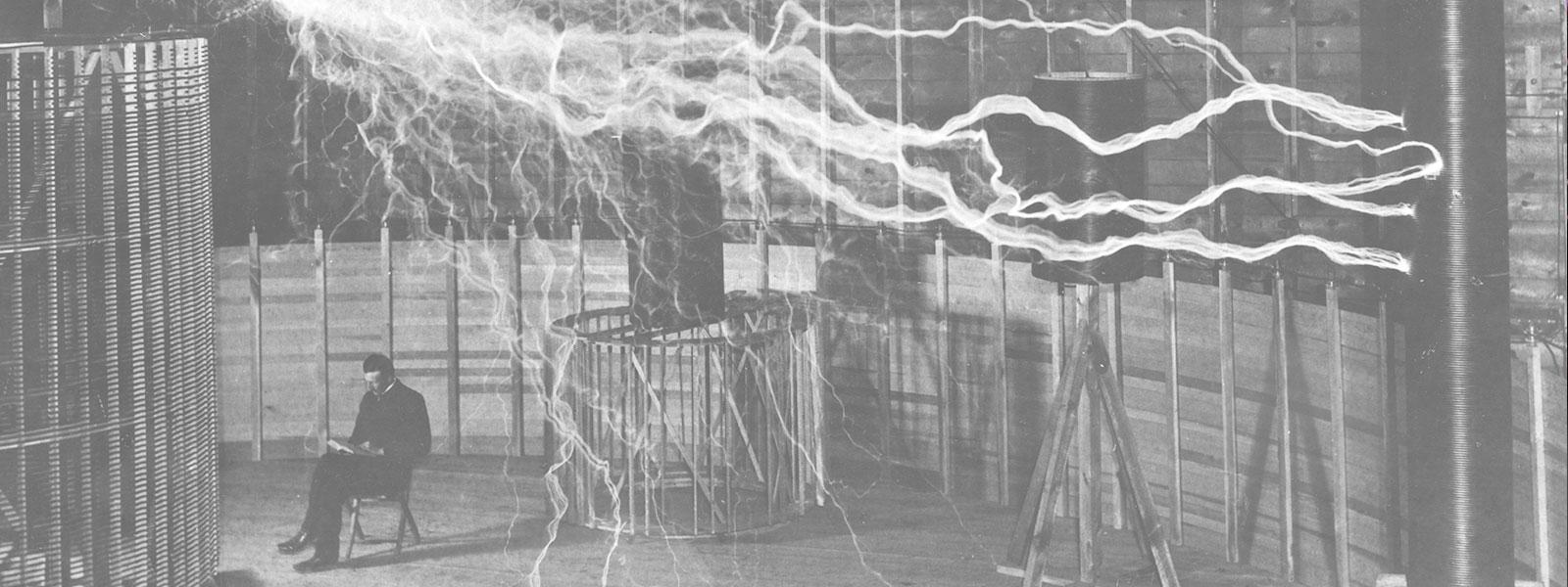
Nikola Tesla News
Tesla Swarm Controller - Part 3 - 64 Tesla Coils?
This is part three of the Tesla Swarm Controller series where we'll discuss the Chinese-made, flat, pancake, dual-resonant Tesla coils and the steps taken to interface with them. In part one of the series, we introduced the project and gave some sneak-peek videos of the swarm in action. Part two goes into the network slaves and the code architecture of the project.
For part three, first, let's face the fact that building Tesla coils is expensive and time-consuming, especially for large coils, plus there's the location to run the coils that must be considered. To have a swarm of large coils is certainly an end goal, but in the development stage, and dealing with the sheer numbers of coils being considered, small is best for now. If I can successfully control multiple, smaller coils, it stands to reason that I can scale or adapt to control larger ones as well.
I have been experimenting with the small, Chinese, pancake coils for a couple of years now. I actually mounted four of them in a flute case and was originally driving them with Phillip's controller. What was odd was that they totally ignored input level, playing each channel at equal levels, and certainly not living up to their full potential.
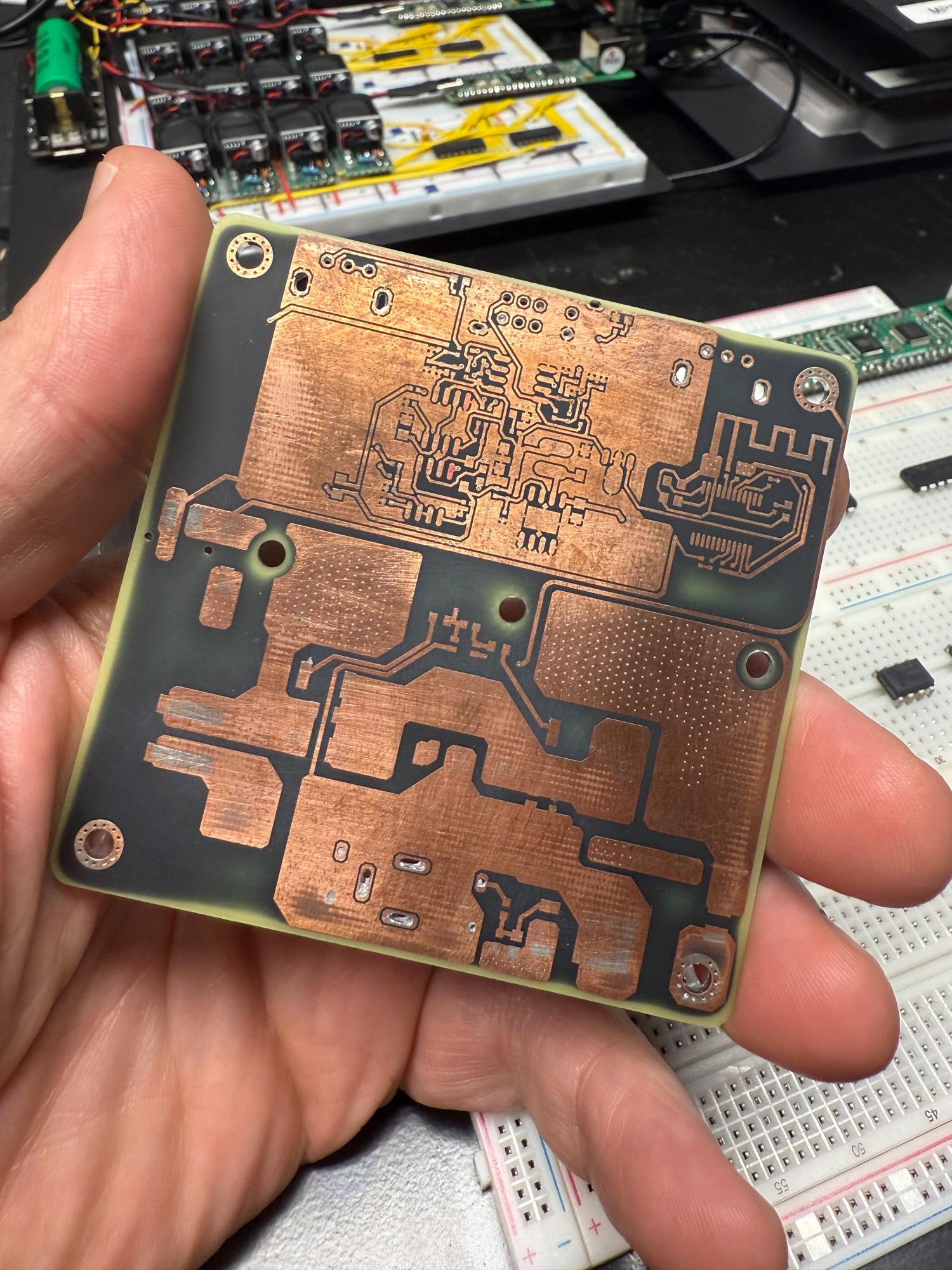
These coils have dual inputs; on-board interrupter provided by two 555 timer ICs and a Bluetooth receiver or 3.5mm input jack for audio, selectable by a switch. One of these 555s acts as a 50% duty cycle oscillator which normalizes the input. This explains the fixed input levels I was seeing originally. The coils also incorporate an LM393 (dual comparator) to act as both a zero-cross detector and an over-temp cutoff circuit (yes, these boards have a surface-mount thermistor mounted opposite the heatsink). I sacrificed one early on to create a schematic, but then they revised it and I had to reverse engineer it again.
The gist is that the drive section of each coil is made up of three stages; soft start, chopper and half bridge. The soft start stage provides a very small delay (< 50ms) to allow the main bus caps to charge without arcing the DC power input or tripping the overcurrent detection in the 48VDC switching power supplies provided with the coils.
The chopper takes the 48VDC bus and pulses it into the half bridge. The chopper's gate is where we tap in with the controller to pulse the coil with the Pico 2's PWM signal. The half bridge gates are driven by a tiny 1:1 transformer, the primary of which is in series with the base of the Tesla coil secondary and ground. This provides the feedback to trigger the half bridge in sync with the Tesla coil. The transformer's secondary drives the two half-bridge MOSFETs, assuming the LM393's over-temp comparator doesn't hold it low. So what happens is when the chopper feeds the 48VDC to the half bridge, it begins to self-oscillate, providing the output discharges from the Tesla coil at the same frequency that is sent to the chopper. Send the chopper a 100Hz 20ms 10v square wave and you'll get a nice 100Hz tone from the coil.
For the Tesla Swarm project, we didn't need the two 555s, the Bluetooth receiver, 5-volt regulator, switches, pots, and supporting components. These were all removed for each coil and a two-pin connector was added to provide ground and chopper gate inputs. The catch was that the chopper needs a 10V drive signal and the Pico 2's 3V logic level just wouldn't suffice. I looked at different ways to bring the level up to the required 10 volts and the UCC27424P dual gate driver seemed to fit the bill. Each slave would need to incorporate a boost converter to raise the 5-volt supply to 10 volts to drive the chopper gates of each coil via the gate driver ICs.
But remember in the prior post I mentioned glitches during frequency and on time adjustments, or note changes in MIDI playback? Now would be the time to address this, before the slaves are actually assembled. After much research, I discovered others running into the same issue. What seems to be happening is that the hardware PWM devices in the Pico 2's are sensitive to parameter changes depending on where the output waveform is at the point of change. In other words, if the waveform has crossed zero, but has yet to peak, and then a parameter change occurs, the PWM doesn't handle the change gracefully, spiking the output for the period until the next peak. It can't safely change parameters mid cycle.
I toiled and toiled over this problem and eventually settled on using 74HC08 AND gates to mitigate the problem. Originally, we'd only be using eight pins from each slave Pico 2 for the PWM outputs, plus the pins for the SPI bus connected to the Wiznet ethernet interface, so we had plenty of pins to spare. What I'd do is dedicate a pair of pins for each output instead of a single; one pin for the PWM and another configured as a boolean to control the AND gate for the given channel. In the slave code, I added a 0.5ms delay to allow the PWM signals to settle before they're fed to the coils. So when a note is playing and a note change instruction comes in, the gate closes, turning off the coil, the PWM update is made, the delay occurs and then the gate opens, turning on the coil. Thankfully, this took care of most of the glitches. It would be more ideal for the gates to operate based on the current position of the waveform rather than a fixed delay. We'll see about this in the future.
So with that, I assembled my first, test slave on a breadboard, still using speakers as stand-ins for the Tesla coils. It worked great! And, it had so much less noise than outputs provided directly by the controller Pico 2. It was as if the ethernet was shielding the slave. I built a second, 8-channel slave on a breadboard, also with speakers. It too worked perfectly and playback sync was good between the two. At first, I was using large packets with all eight channels being sent any time any channel needed enabled/disabled. After testing, this proved less than ideal on complicated songs. What worked much better was sending very small packets, specific to individual channels, only when they needed enabled/disabled. Of course a keep-alive protocol was developed as well, for continuous mode and extremely long notes. This will help keep things safe in case of loss of communication.
Once I had two slaves working on breadboards, I wondered how many I might build. I had already ordered 32 Tesla coils, but could it do more? I needed more parts to build additional slaves anyway, so I ordered 32 more coils as well and decided on the target of 64 coils. While I waited, I built as much as I could with what I had on hand and then switched to interfacing the coils to the slave. The flute case coils used fiber, mainly because Phillip's controller has fiber outs. If you haven't noticed, those fiber receivers, and transmitters, are expensive. So that was not something I was willing to do for 64 coils. In the flute case coils set up, I was already using CAT5 between the fiber receivers and the coils, so it made sense to try it for the slaves.
I connected eight coils to the first completed slave using one twisted pair of stranded wire for each coil. I used the original, separate power supplies for the coils at first for testing. The slave was powered up and I slowly brought up the pulse width on the controller. I could see the packets flying on the network indicators. Then, a faint buzz. I kept turning and there they were, all eight coils making nice sparks. I kept going and could easily reach the same outputs as the original, on-board interrupter, and then some!
Next time, we'll discuss power supplies and power distribution for the Tesla coils. We'll also begin to describe the operations of the controller, including the new level save functions. In the meantime, take a look at the gallery of build photos I've put together as well as this short clip of the flute case quartet: