Plans
Level-Shifted Tesla Coil Designs
A device called a level shifter enhances the output of Tesla coils. Several options for level-shifting designs are outlined.
About four years ago, Dave Sharpe from Virginia built and demonstrated a tube Tesla coil project that incorporated a special circuit he referred to as a level shifter. The level shifter creates a constant bias voltage on which the output potential, pulsed or waveform, piggybacks. The circuit in the demonstration was built into the power supply. By raising the reference voltage of the oscillator, it increased output by about 10-15%.
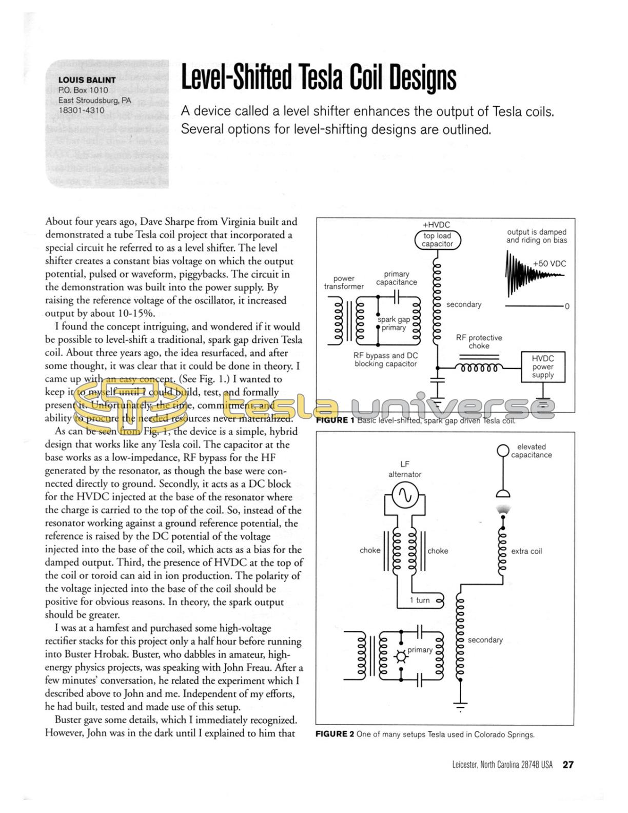
I found the concept intriguing, and wondered if it would be possible to level-shift a traditional, spark gap driven Tesla coil. About three years ago, the idea resurfaced, and after some thought, it was clear that it could be done in theory. I came up with an easy concept. (See Fig. 1.) I wanted to keep it to myself until I could build, test, and formally present it. Unfortunately, the time, commitment, and ability to procure the needed resources never materialized.
As can be seen from Fig. 1, the device is a simple, hybrid design that works like any Tesla coil. The capacitor at the base works as a low-impedance, RF bypass for the HF generated by the resonator, as though the base were connected directly to ground. Secondly, it acts as a DC block for the HVDC injected at the base of the resonator where the charge is carried to the top of the coil. So, instead of the resonator working against a ground reference potential, the reference is raised by the DC potential of the voltage injected into the base of the coil, which acts as a bias for the damped output. Third, the presence of HVDC at the top of the coil or toroid can aid in ion production. The polarity of the voltage injected into the base of the coil should be positive for obvious reasons. In theory, the spark output should be greater.
I was at a hamfest and purchased some high-voltage rectifier stacks for this project only a half hour before running into Buster Hrobak. Buster, who dabbles in amateur, high-energy physics projects, was speaking with John Freau. After a few minutes' conversation, he related the experiment which I described above to John and me. Independent of my efforts, he had built, tested and made use of this setup.
Buster gave some details, which I immediately recognized. However, John was in the dark until I explained to him that the basic concept of operation was to level-shift the coil. Then, he recognized the concept from his own work with tube coils. Buster said that the spark output had increased and was unusual in appearance. Having applied both negative and positive voltage, relative to ground, at the base of the coil, he naturally obtained the best results with positive polarity.
What he said next completely floored me. He said he needed good, insulated shoes while powering this project because it was somehow charging up his concrete floor in the basement where he was running it, and if he did not have the correct footwear on, he felt shocks at the bottom of his feet and worried about electrocution. I subsequently visited Buster, and he demonstrated his project. The operation was as described with one important exception. The charging of the grounded floor around the apparatus was mostly due to the faulty ground wiring in his basement, in combination with the connection of one of the two hot-side terminals of the supply transformer for the DC supply to the ground connection. The result was a hot-ground level of around 8000 VAC.
The HVDC was unfiltered, except of course by the capacitor that was connected to the base of the coil and to ground. It is a glass plate type and I would rate it at no more than 0.01 uF, which means it would have a large 60 or 120 cycle ripple at the top capacitive load.
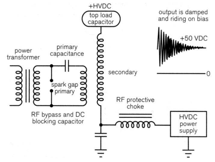
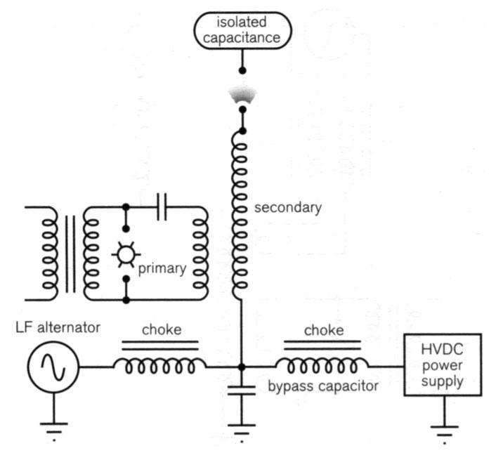
This is reminiscent of previous investigations regarding Tesla's power transmission apparatus and electrostatic field modulation, including James and Kenneth Corum's 1996 paper, "Spherical Transmission Lines and Global Propagation." In this paper, the Corums disclosed that Tesla may have used the top turn of the 50-ft diameter primary/secondary transformer structure at the Colorado Springs laboratory to couple a low-frequency alternator to the transformer. This would modulate the electrostatic charge accumulated on the isolated, elevated isotropic capacitor structure, that is commonly mistaken to be an antenna, in order to pump this charge at a frequency that would be favorable to establish a resonant mode for global propagation. (See Fig. 2.)
Regardless, a large, low-frequency ripple at the top capacitive load, may be able to modulate the static field around the toroid and affect nearby objects. To continue on this premise, I now present plans for low-frequency injection to modulate the system that differs from (a) the use of ripple from the DC power supply; (b) the Corums' and Tesla's use of a single-turn coil to couple a low-frequency alternator into the secondary coil; and (c) the use of the 60-cycle signal from the output of the power transformer that drives the Tesla coil, albeit power transfer will be minimal at 60 Hz due to use of an air core.
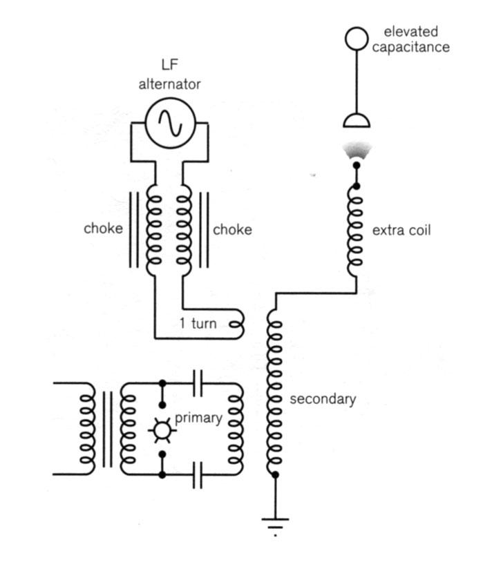
Referring to the first plan, the HVDC power supply is deleted, and in its place is a low-frequency alternator, connected to the base of the secondary with a properly chosen bypass capacitor. (See Fig. 3.) The alternator frequency can be varied to suit the conditions. The Corums suggest operating it around 1100 Hz.
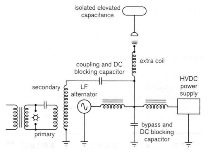
The second plan is a composite of the two methods mentioned above. (See Fig. 4.) The low-frequency alternator is still used, and a filtered or non-filtered HVDC power supply is connected to the base of the coil, as shown. I see this as probably the best circuit design, although a multitude of variations will also work, such as the magnifier setup shown in Fig. 5.
The output voltage from the alternator could, of course, be boosted by a transformer interfaced between the output of the alternator and the base input to the coil. Maximum output will be a function of the properties and conditions of the material used. Just as the HVDC can be increased, extra alternators can be added and operated at different frequencies to produce beats and complex waveforms if desired.
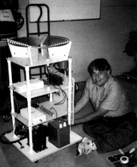
Whatever method is used, the results could be interesting, and as a word of caution, deadly. What little time I had available to myself preceding the RATCB (Rochester Association of Tesla Coil Builders) Teslathon in August, I dedicated to constructing my concept of the level-shift, base-injected resonator. (See Figs. 6-8.) It turned out to be a success, both in meeting my performance expectations and in its presentation to the group in Rochester. It was greeted with great enthusiasm, leaving several individuals shaking their heads in wonderment as to why nobody had considered exploring this concept until now. Several in attendance were in agreement that many misconceptions abound about the physical universe. Nobody expected these results, only because nobody had investigated this concept, to my knowledge.

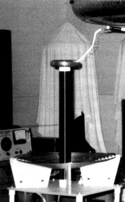
I cannot understate the performance of this device, not so much in level shifting as in power delivery, as evidenced by the spark display. An air core transformer can transfer no better than 50% of its power between its primary and secondary at high frequency. The transfer becomes less efficient as the applied frequency is lowered, necessitating the use of an iron core. However, to circumvent this drawback at high frequencies, the resonator may be base injected using any type of power source. With direct coupling, power transfer can be as much as 95% efficient. One primary limiting factor will be the diameter of the wire used in the resonator. Obviously, a larger wire diameter will lower the resistance, increasing current flow. Thus, more power will be transferred to the output terminal.
Another interesting feature is the spectral output of the system. (See Fig. 9.) Standard Tesla coil operation generates a high-voltage, high-frequency component. However, when a low-frequency power component is injected into the resonator where it is accelerated by the action of the high-voltage output, fast electrons are detected at the output terminal, much like those in a linear accelerator.
It occurred to me that if the low-frequency power supply at the base of the resonator were to be replaced by a DC source, a low-frequency power component would still be produced, if a power arc is established between C2 and the grounded target at SG2. L2, Cdistributed, and C2 are the main components of the resonator structure for the generation of a high-frequency, high-voltage output, when C1, and L1, are equally tuned to resonate the secondary structure. C3 can be ignored, for its primary function is that of RF bypass for basic Tesla coil operation.
Now consider the low-frequency aspect of the device with the HVDC power supply charging C3. Components C3, L2, Rs and SG2 become the major players. When a power arc is established as stated above, these components form a series resonant, LCR lumped circuit, resulting in a spectral power component separate from the high-frequency one, as stated above. The components C2 and Cdistributed can be ignored except in large systems. Yet they simultaneously share the same values and circuit path for LF and normal coil operation.
As an example, when the values for the various components are computed, the high-frequency component for the secondary coil resonant structure will be around 290 kHz at critical coupling or after SG1 stops conducting, for over-coupled systems under normal Tesla coil operation. When an arc is established at SG2, the resonant frequency for this part of the circuit will become 15.9 kHz. Power is limited by the losses inherent within the system.
Now consider a transmitter the size of the Colorado Springs or Wardenclyffe tower, and extrapolate some reasonable values for its components. (See Fig. 10.) Again, L1/C1 and L2/C2 form the high-frequency, high-voltage component, which outputs 50 kHz, and is considered incidental to the purpose of generating the high-voltage in this design. The power frequency, at which Schumann resonances can be easily obtained, comes from L2/C3 and SG2, where C3 translates the power delivered from a capable multimegawatt source into a low-frequency, high-power output through the ground return.
Building and operating a high-power, low-frequency transmitter is fairly easy. However, the minimum power requirements to launch successful global resonances for transmission, and the best method for this launch, if at all possible, remain daunting unknowns to this day.