Plans
Make a model Tesla Turbine
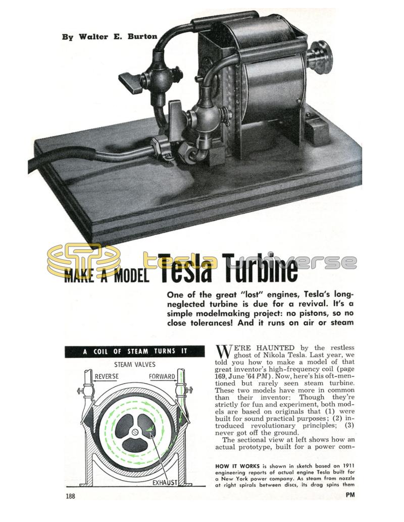
One of the great "lost" engines, Tesla's long-neglected turbine is due for a revival. It's a simple modelmaking project: no pistons, so no close tolerances! And it runs on air or steam
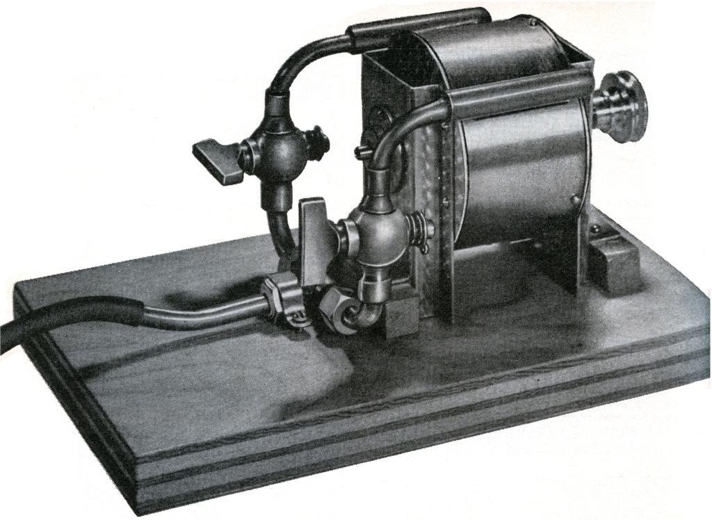
We're Haunted by the restless ghost of Nikola Tesla. Last year, we told you how to make a model of that great inventor's high-frequency coil (page 169, June '64 PM). Now, here's his oft-mentioned but rarely seen steam turbine. These two models have more in common than their inventor: Though they're strictly for fun and experiment, both models are based on originals that (1) were built for sound practical purposes; (2) introduced revolutionary principles; (3) never got off the ground.
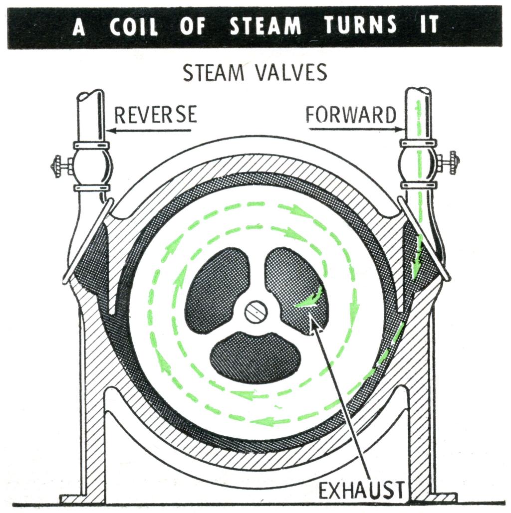
The sectional view at left shows how an actual prototype, built for a power company, worked. It had 25 discs 1/32 in. thick, and though it measured only 2 ft. by 3 ft. and stood only 2 ft. tall, it produced 200 horsepower at a speed of 16,000 rpm on a125-lb. steam pressure. The spiral path o the steam was as great as 16 ft., and the pressure of the exhausting steam was a low as 1 psi - proof of the turbine's remarkable efficiency.
The other feature that created a lot of excitement at the time (pre-World-War-I) was the ease with which the engine could be reversed. You simply fed the steam to a nozzle on the opposite side of the rotor shaft. Standard turbines of that day could only be reversed through a complex, clumsy process.
But Tesla's turbine never went into commercial production. Maybe it was just ahead of its time. There are hints that interest in it is reviving; the Navy Department is taking a fresh Look at the turbine for example. It may yet become an important power unit - perhaps in conjunction with atomic steam plants.
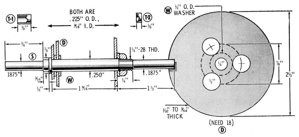
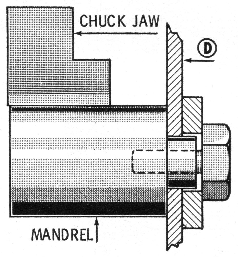
The operating principle that stimulated all this abortive interest in 1911 is beautifully demonstrated in our model. The Tesla rotor consists of parallel discs on a shaft, spaced apart a distance equal to or slightly greater than their thickness. In Tesla's full-sized turbine, these discs were of hardened steel; but since you'll be operating the model at only modest pressures you can use easily-worked aluminum.
A jet of air (or steam), directed toward the edge of this rotor assembly, spirals around the spaces between the discs in an effort to find the central escape ports. The drag of the gas against the faces of the discs causes the entire rotor to spin.
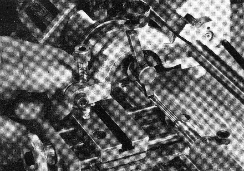
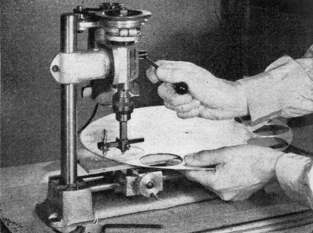
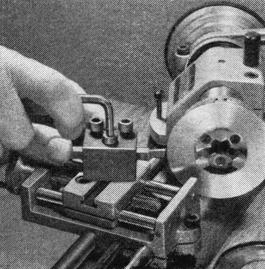
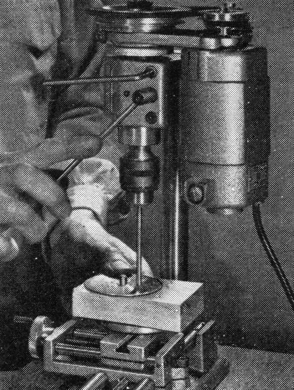
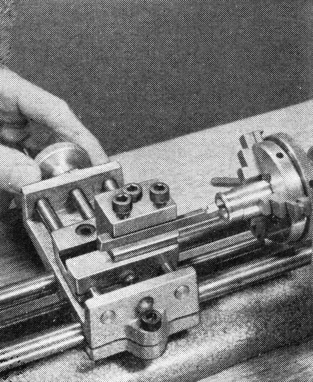
Our model perches its 35-oz. weight and 3½-in. height on a 5 x 8-in. platform of ¾-in. plywood. If you're going to run it an air, you can make the turbine out of almost any metal, using a tin can for the housing (C) and cold-rolled steel for the shaft (S). But if you plan to introduce steam, you'll want a housing of aluminum and a shaft of stainless steel. All the machining for a model of this size can be done on a small metalworking rig, such as the Unimat shown in all photos, left.
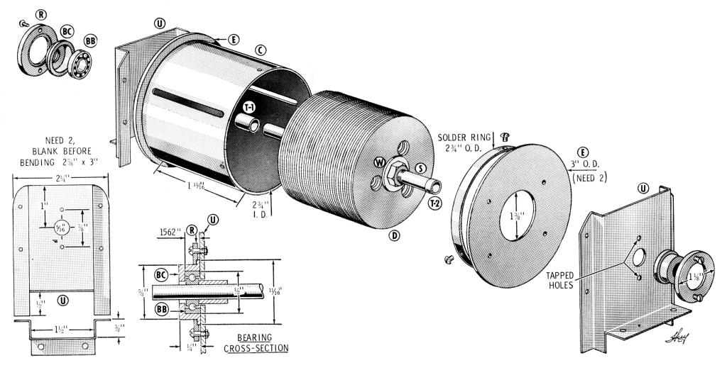
The housing cylinder for our model was cut from an old brass fire extinguisher. If the cylinder you choose is oversize and must have a segment removed - or if you have to make a cylinder out of flat sheet - join the ends with a metal strip riveted across the joint and sealed with solder. If you make the housing of aluminum, assembly can be by means of riveted brackets, instead of soldering. At any rate, it's a good idea to leave one end plate detachable so you can adjust the rotor, later.
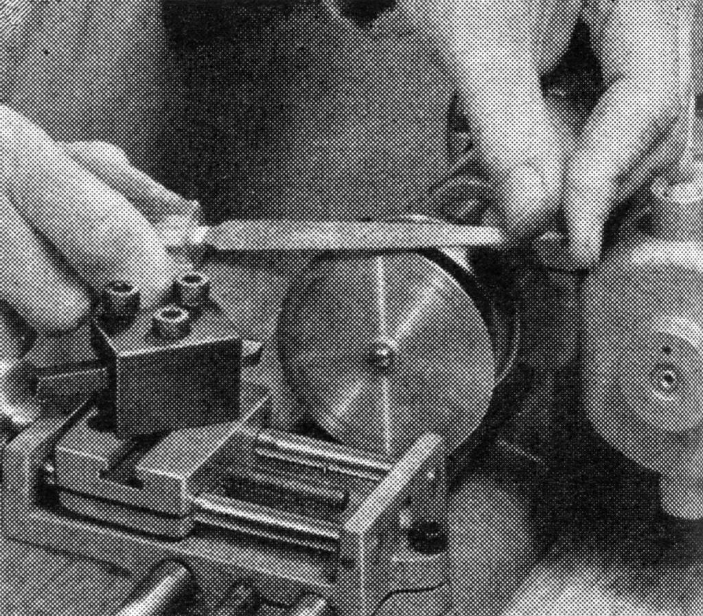
The housing is suspended between two uprights (part U) which also support the rotor bearings. The uprights should be made of fairly stiff material, such as 18-ga. (.0403-in.) brass. Four short 2-56 screws attach each upright to the end plate. In our model, these parts are polished to an "engine-finish" by means of an abrasive-rubber rod chucked in a drill press. The channel between upright and plate lets exhaust escape.
Fafnir No. 33K5 ball bearings were used on the model shown; this bearing has a ½-in. O.D., a 5/32-in. width and a 3/16-in. bore. If similar bearings are not available, you'll have to alter affected dimensions - or machine solid sleeve bearings from ¾-in. bearing-bronze rod.
Whichever type of bearing you choose, attach it to the upright with a couple of 2-56 screws through a retaining ring and into tapped holes in the upright. Lock washers on the inside keep the screws from backing off under vibration. Note in the cross-section on page 189 that the retaining rings are recessed for the bearing cap but not set tight against the upright.
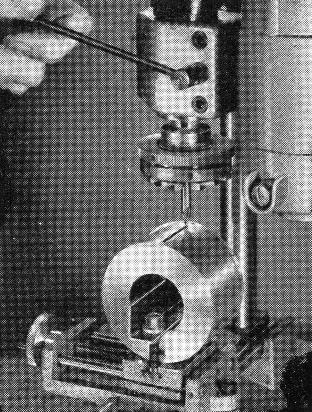
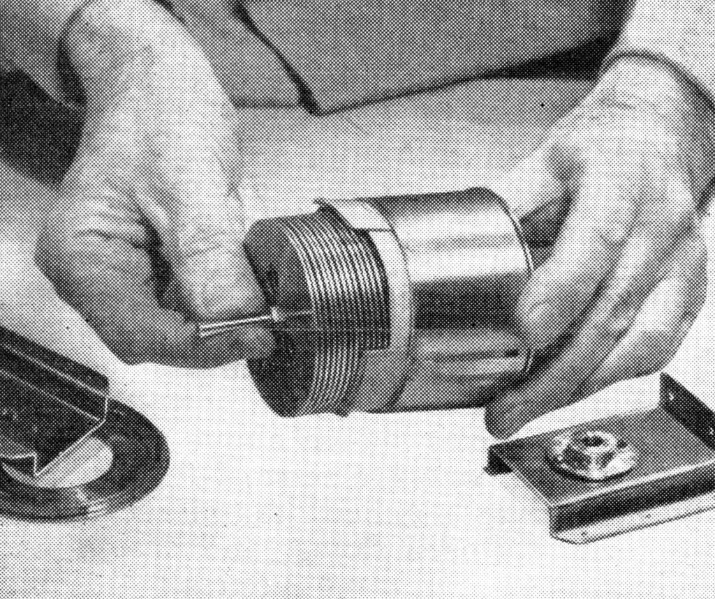
Positioning the hearings with respect to the rotor shaft is demonstrated in the bottom photo on the previous page. After the bearings are mounted on the uprights (centered over the 5/16-in. holes), place the rotor in the housing as shown, press the loose end plate in place, and suspend the shaft between the bearings to locate the mounting holes in the end plates. If the shaft won't turn freely when the assembly is complete, change the bearing alignment by loosening or tightening the retaining ring screws, or by inserting shims between uprights and end plates.
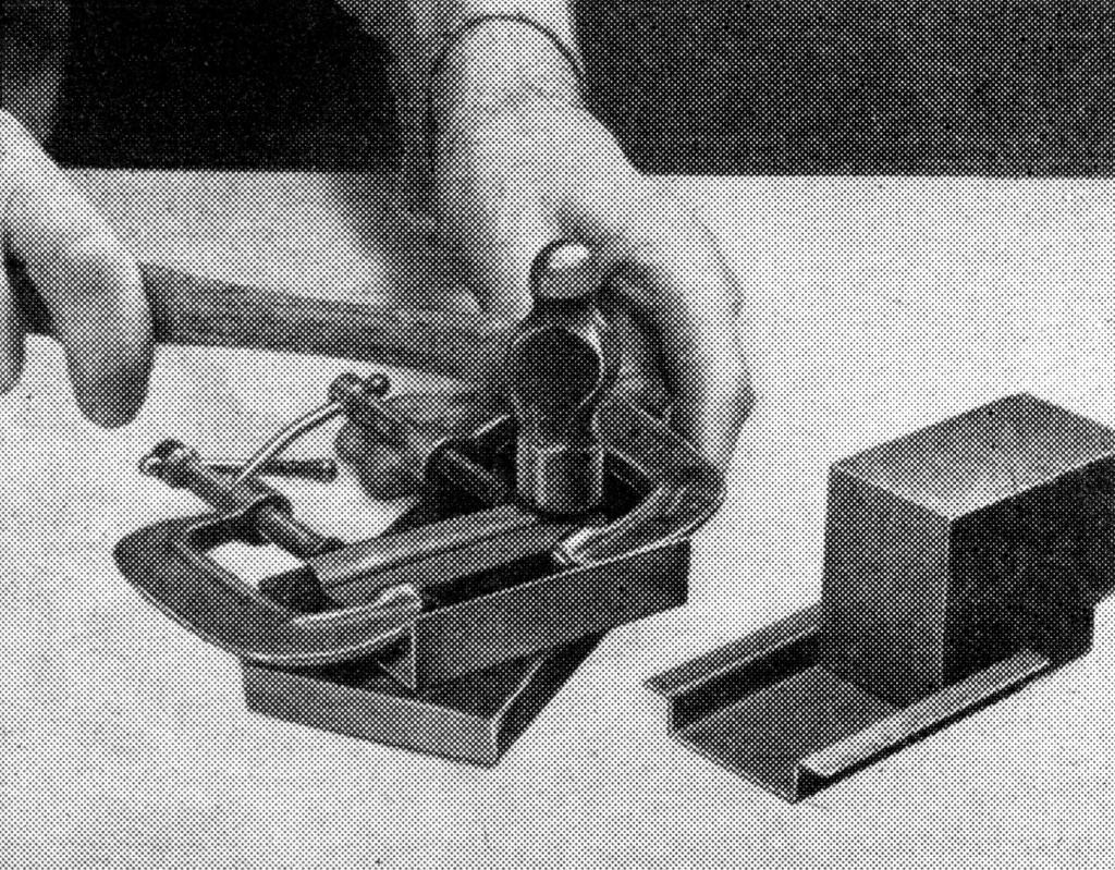
Remember, too, that discs and washers must be flat; one way to flatten them is to sandwich each one between steel plates, before assembly, and strike the top plate with a hammer.
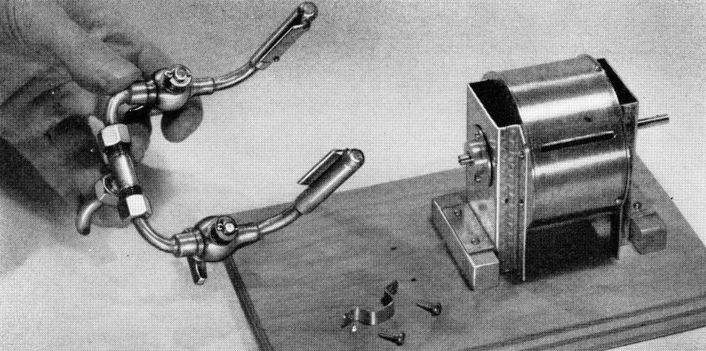
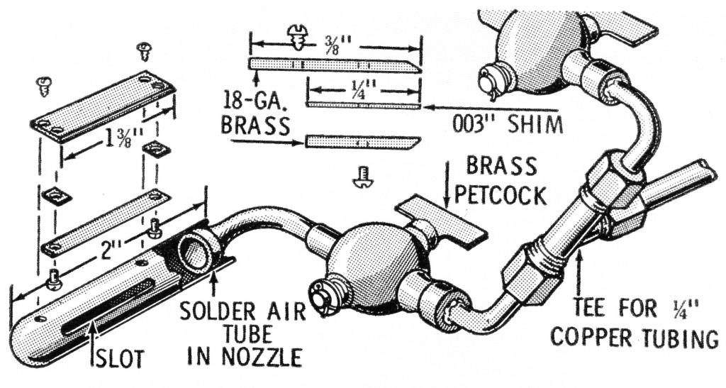
The air boxes shown above were made from 1/8-in. brass electrical-fixture pipe. One end was notched, hammered inward to form a closed dome, and sealed with solder. You can save yourself this step if you can locate 2-in. sections of pipe or tubing with one closed end. The discharge port should be a slot about 1⅛-in. long and 1/32-in. wide - or it can be a series of closely-spaced 1/32-in. holes, instead. Now, weld over each discharge port a nozzle formed by screwing and welding plates together with edge-shims to form a slit, as shown in the sketch.
The slots in the housing (C) that take these nozzles should be cut after the jet assembly is complete. They're located at about the 10 and 2 o'clock positions (think of the end plates as clock dials). Direction of rotation depends on which jet is turned on, so petcocks are soldered into the feed lines. To simplify the unit, you can make a single nozzle for one-direction operation. This could be soldered directly to the housing slit.
This model is not intended for high-speed operation on high-pressure air or steam. Under such stress there might be hazards involving tensile strength of rotor discs and other parts. But the model shown has run merrily for months when hooked directly to a ¼-hp air compressor; at comparable pressure, it will perform similarly on steam.
Materials List
| Part | Key | AM‘T | Description |
|---|---|---|---|
| Uprights | U | 2* |
18-ga. brass 2 7/8" x 3" |
| Housing | C | 1* | Cylinder approx. 2 3/4" I.D. x 1 3/4"; or 18-ga. brass 1 3/4" x 8 3/4" to form cylinder |
| Housing ends | E | 2* | 18-ga. brass 3" x 3" |
| Solder ring; air-tee strap clamp | 1 | 18-ga. brass 1/4" x 12" makes both | |
| Shaft | S | 1 | 3/8" x 4" c.r. steel rod (or stainless alloy) |
| Rotor disks | D | 18** | 18-ga. aluminum discs 2 1/2" dia. |
| Rotor washers | W | 20** | 18-ga. aluminum discs 1/2" dia. |
| Nut | 1 | 1/4"-28 brass hex | |
| Bearing caps | BC | 2 | 3/4" brass rod, 1" long makes both |
| Bearing-retaining ring | R | 2 | 18-ga. brass (or heavier) discs 1 1/8" O.D. |
| Ball bearing | BB | 2 | Fafnir 33K5 or equivalent |
| Rivets | 12 | Small brass escutcheon pins, or equivalent | |
| Screws |
18 6 |
2-56 x 1/4" R.H. brass machine; four matching nuts #3 x 1/2" R.H. wood |
|
| Sleeves | T-1, T-2 | 4 | 1/4"-O.D. copper tubing reamed out with No. 12 twist drill |
|
|
|||
| Air boxes | 1/8" brass pipe 4 1/4" long | ||
| Air-jet plates | 4* | 18-ga. brass blank about 1 1/2" x 1 1/2" | |
| Spacing washers | 4 | Bronze shim stock 0.003" x 1/4" x 1" | |
| Tubing | 14" | 1/4" copper | |
| Tee | 1 | To accept above tubing; or make a "T" or "Y" arrangement by hard-soldering pieces of tubing | |
| Petcocks | 2 | Small brass, as shown in photos | |
|
Sleeves for joining petcocks and tubing |
About 3/4" of 1/4"-I.D. copper tubing | ||
| Base |
1 2 |
3/4" x 5" x 8" plywood or solid stock 1/2" x 1/2" x 2 1/2" wood blocks |
|
|
Small brass or aluminum pulley |
1 | 3/16" bore | |
*Total size of brass sheet parts C, E, U, etc.: 5 1/2" x 12"
**Total size of aluminum sheet for disks, washers: 11 1/2" x 14"
