
Plans
New and Improved Tesla Coil
There is nothing so fascinating and instructive to the science student and experimenter as a Tesla coil. This was originally developed by the electrical genius, Nikola Tesla, in the 1800s. He demonstrated his coil at many lectures abroad and when he came to this country, a large model was built in an attempt to broadcast electrical power to a distance without using wires. The plan failed however, due to the comparatively low efficiency, lack of directional control and other factors.
The Tesla coil is a generator of high voltage at high frequency. It is capable of weird effects not possible with any other apparatus. It is no wonder that most science fairs have one or more Tesla coils among the exhibits which many times have won awards!
The early coils of Tesla's time employed spark gap oscillators, Leyden jars and such insulation as parafin and guttapercha. Today, we can use the more efficient vacuum tubes as oscillators, high quality mica capacitors and high voltage insulation such as plastic and Bakelite, all of which are featured in coils of modern design.
The model to be described here was designed to retain the good features of the popular "souped-up" coil, built by many science students over the past several years, but with improvements that result in simpler construction, lower cost and smaller size. Among other things the 5514 tubes that are now obsolete have been replaced with 811-As. A standard, lower cost plate transformer is employed and the hard-to-get mica transmitting capacitors have been reduced to one unit in a size that is available from a source given in the materials list. The other required capacitors are the familiar TV door-knob type which are available from most electronic supply dealers. All parts connections and wiring that should be protected from accidental contact, are contained in a hollow plywood base and the tubes, plate transformer and wound coils are mounted on a top Bakelite panel. The design is neat and compact with a feature that allows the tall secondary coil to be easily unscrewed for removal when it is desired to move the coil. (To the Science Fair.)
Constructing The Coil
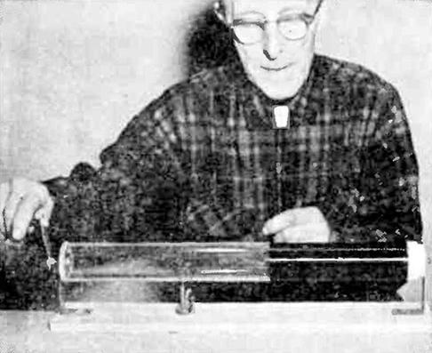
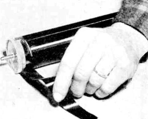
The drawings and photos make all details of the construction clear. Start work on the tall coil, L-3 which is wound on a plastic tube, using a simple handwinding jig. This is shown in Fig. 1. It has a wood base and two heavy sheet metal side brackets with a hand crank for winding. Fit a tapered wood plug in one end of the tube so a wood screw used through a hole in the bracket will support this end. Equip the other end with a plastic disc secured in the tube with small machine screws. It has a ¼-20 bolt in a center hole to which the crank is attached with two clamping nuts. Details of this disc are given in the drawings. Start the winding with #32 Formvar wire about ½-in. from the end and hold the end of the wire with a band of paper masking tape. Put the turns on in an even layer avoiding laps in the turns or spaces between them. Care must be taken also to avoid breaking the wire as it is quite fragile. The spool of wire should be mounted on a suitable support between the operator and the bench so it will come off the spool easily without kinks. If it is necessary to stop for any reason, place a band of tape around the last turns to hold them.
Continue winding for a distance of 17 1/2-in. which should bring it around 1/2-in. from the finish end of the tube, with the result that about 1900 turns be put on, although it is not necessary to count them. Bore a hole through the plastic tube at each end just beyond the last wire turns of a size that will pass small spaghetti tubing of about 1/16-in. diameter. Solder short flexible leads to the start and finish ends of the wire and carried through the holes for connections.
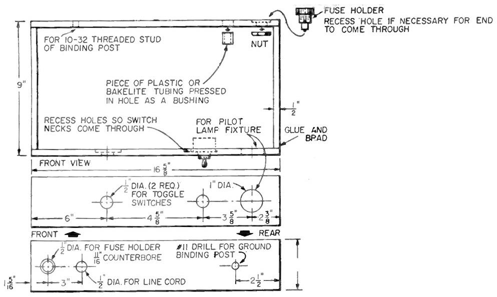
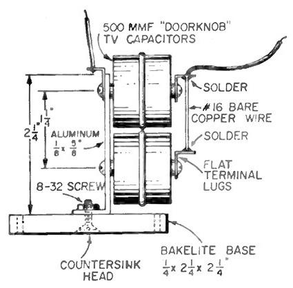
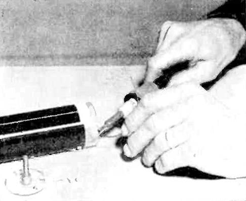
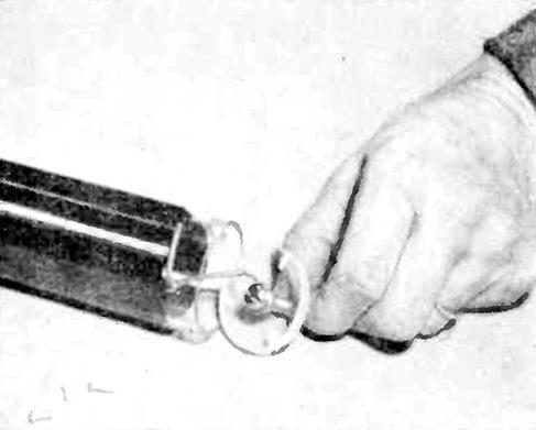
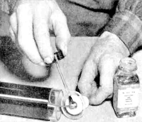
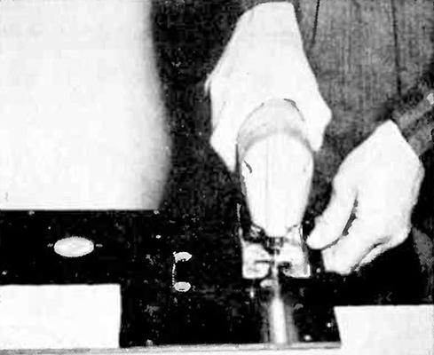
Figure 10 illustrates the soldering of the lead at the lower end of the coil. Be sure to clean off the wire insulation by holding a match under the end a second or two and then use fine sandpaper. Trim off the end of the plastic covered lead and make a neat splice. Place some spaghetti tubing over the lead, completely covering the spice and then pass it through the hole and connect tightly under the screw head. Fig. 11 shows it connected as described.
A second plastic disk is now made, having a center hole to clear the nut on the screw and this is attached to the first one with Pliobond cement. Apply a band of plastic tape around the end of the tube, covering the first turns and tightly binding the spliced lead, as shown in Fig. 12.
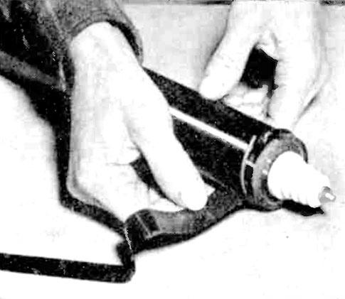
At the top end of the coil, fit a porcelain insulator to a plastic disk with a long screw and nut and connect the spliced lead to this screw. Apply some varnish or shellac to the bare screw head as shown in Fig. 13 to help prevent corona discharge here. The disk is secured in the tube with cement.
Apply plastic tape around this end of the tube over the last wire turns and the splice. To make a better appearance, place a short piece of the spaghetti tubing around the tube, with the ends meeting the tubing over the lead to make a continuous bead around the tube, as illustrated in Fig. 14.
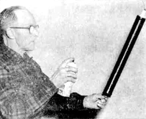
To complete L-3 apply two coats of varnish from a pressure can, allowing each coat to thoroughly dry. This is shown being done in Fig. 15. Do not use a lacquer-base varnish which might attack the wire insulation and thus detract rather than add to the insulation value. Apply the varnish in light coats, avoiding runs and sags.
The Other Coils
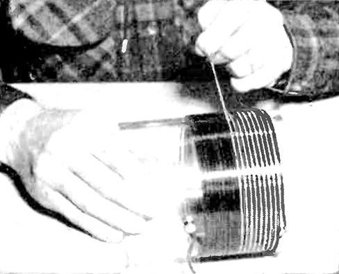
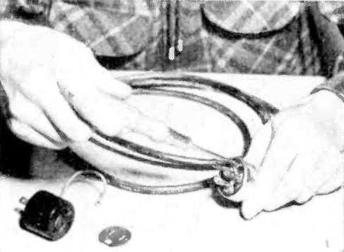
Wind L-1 and L-2 on a 4½-in. diameter plastic tube with L-1 at the bottom and spaced about ½-in. from the edge. Two binding posts are provided with 6-32 screws and nuts in drilled holes for the heavy winding terminals. Two #15 wires wound in parallel are used with string pulled between the turns to slightly separate them. Fig. 16 shows the string being applied. Clean the ends of the wire thoroughly, form them into loops and attach under the nuts. The string can be tied to the terminals to hold in place.
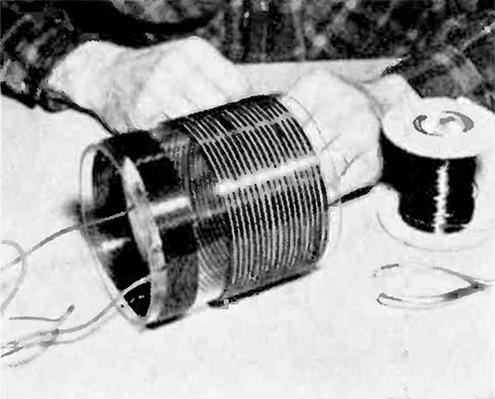
Form L-2 above the first winding, leaving a space of about ¾-in. using #20 wire which also has heavy thread or light string between the turns. Both coils have 18 turns. The ends of this winding are equipped with spaghetti tubing and carried through drilled holes in the plastic tube to the inside and from there they go directly into the base. Flexible leads of #16 wire are connected to the terminals of L-1 and these leads are also carried down to the base section. Fig. 17 shows both coils completed.
Both coils wound on the same form are now finished. Wires are brought to the base.
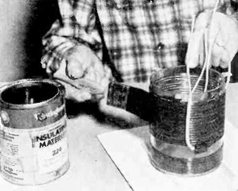
Apply two coats of insulating varnish to the entire unit as illustrated in Fig. 18. This can be sprayed on or applied with a brush. Note that three small aluminum brackets have been made up and attached to the lower edge of the tube with small machine screws for attaching the unit to the Bakelite panel.
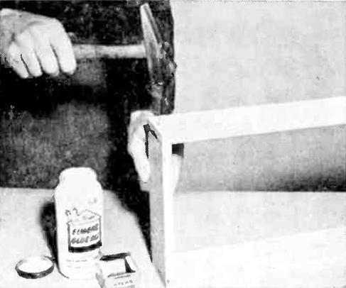
Make the base from ½-in. fir plywood which is glued and bradded together as shown in Fig. 13. It will be found somewhat easier to make the required openings before assembly but they can also be made later.
Assembling The Unit
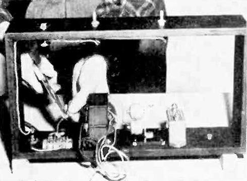
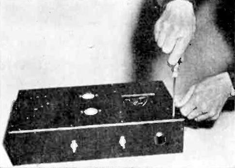
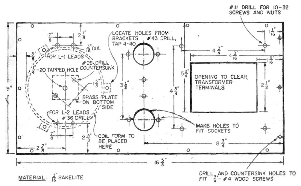
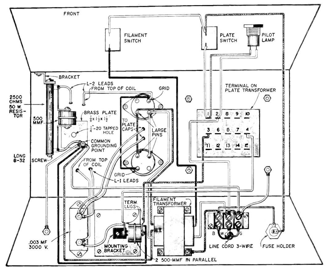
The Bakelite panel requires a number of holes and openings, the largest one being to clear the plate transformer terminals. Cut this out on a jig or band saw. (A saber saw is shown in use in Fig. 22.) Before attaching the top panel, mount some of the parts to the sides of the base as in Fig. 19, where the filament transformer, capacitor support, .003 mfd. mica capacitor and line terminal strip are shown. The parts that come through the sides are also seen in place. A few of the connections can also be made at this time as illustrated in Fig. 20. A three-wire line cord and plug are used as a means of grounding the transformer frames for safety and providing a ground connection for the circuit.
Attach the Bakelite top with short oval or flathead screws as shown in Fig. 23. Then mount the parts in place.
The connections at the three-wire plug are illustrated in Fig. 24 and the drawings. The green wire connects to the long prong at the green colored screw and the other two go to the brass and silvered terminal screws. An adapter is shown on the bench for use where the modern grounding receptacles are not found. Connect the pigtail lead under the receptacle plate screw to provide the necessary ground.
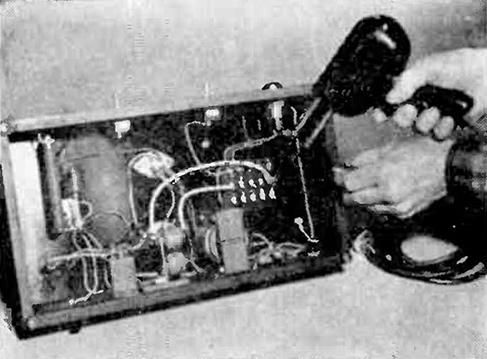
A view of the underside of the base with all wiring completed is given in Fig. 25. The final connection at one of the high voltage transformer terminals is shown being soldered. Protect the leads from these two terminals with some plastic spaghetti tubing where they cross over to connect to the capacitor unit.
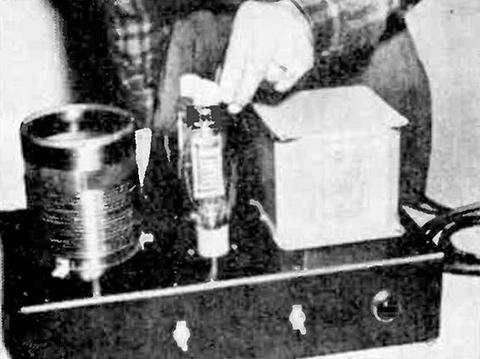
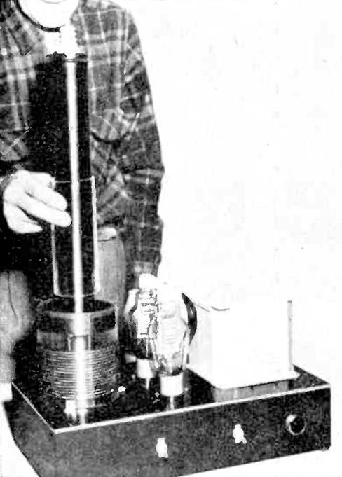
Figure 26 is a top view showing the tubes in place and the plate caps being put on. Fig. 27 shows the use of a piece of plastic tubing that is slipped down over L-3 and allowed to rest on the Bakelite top. It acts as added insulation between primary and secondary windings to help prevent a possible breakdown. The tall coil, L-3 simply screws down in the threaded hole provided in the brass plate at the underside of the top, no further connections being necessary.
A view of the completed coil from the back is given in Fig. 28, which shows the line cord, fuse holder and ground terminal. The top corners of the transformer have been bent down lightly with a hammer for better appearance, since these mounting tabs are not required for this job.
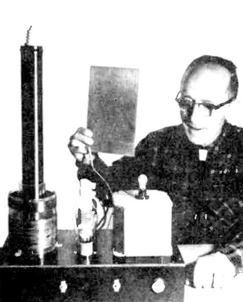
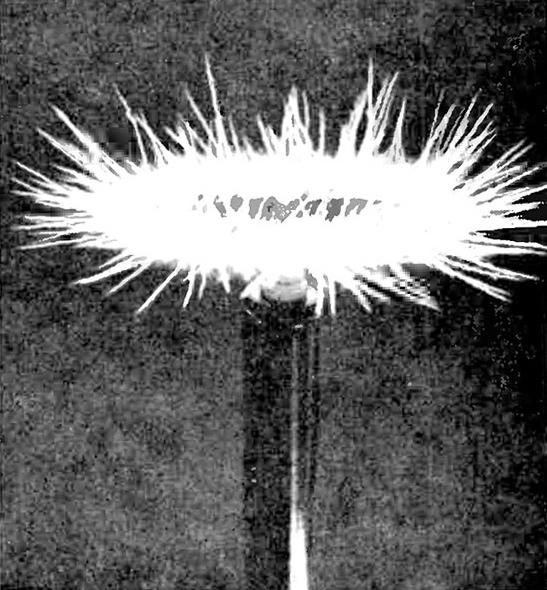
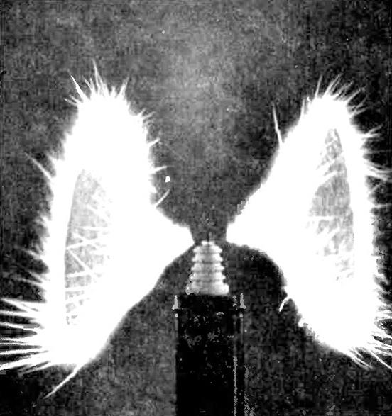
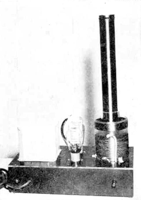
Figures 4 and 5 illustrate some of the experiments that are familiar to most Tesla coil experimenters. The brush discharge from the top terminal is shown. Fluorescent lamps are lighted when held in the hand, a small 120-volt incandescent lamp is lighted from energy picked up by a piece of sheet aluminum as an antenna and pinwheels of electrical fireworks are produced which are especially effective when seen in a darkened room.
While the voltage is high of probably around 60,000 volts or more, the high frequency prevents shock upon contact with the output discharge, but painful burns are possible from the heat at contact. Take care to avoid contact with any parts or connections in the base where conditions could be such as to produce a shock. Be sure to remove the cord before touching anything in this area.
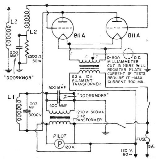
While it is difficult to measure the voltage due to the high frequency that prevents accurate measurements on ordinary instruments, the frequency can be calculated. Determine the inductance of the coil, L-1 and the capacitance used across it or .003 mfd. is the second factor. By using a Shure cardboard reactance slide rule, obtainable from many electronic supply concerns at low cost, the resonant frequency can be found. In our case a reading of .5 megs. (500 kc or 500,000 cycles) was obtained by this calculation.
When operating the coil, be sure to turn on the filament switch first and allow about 20 seconds before turning on the plate switch. It is not good for the tubes to operate them otherwise. Do not operate the coil continuously as the tubes and other components may become over heated. Turning the switches off periodically will allow them to cool off and result in longer life.

Materials List - New, Improved Tesla Coil
| . | Electronic Components |
| Amt. Req. | Size and Description |
| 1 | 1200-v. 300 ma. secondary power transformer UTC S-42 |
| 1 | 6.3 v. 10 a. filament transformer. Thordarson 21F12, or equivalent |
| 1 | 2500 ohms, 50 w., non-adjustable Ohmite resistor |
| 3 | 500 mmf. 20,000 v, TV door-knob type capacitors |
| 2 | 6 amp. at 120 v. s.p.s.t. toggle switches, with solder terminals |
| 2 | ON-OFF toggle switch plates |
| 1 | 120 v., 6 w., lamp pilot light assembly for 1" red jewel |
| 1 | 6 w. 120 v. pilot lamp, candelabra base |
| 1 | porcelain insulator Johnson 135-45. Use top section only |
| 1 | 3AG fuse holder, panel type with finger knob |
| 1 | 3AG 5 a. Slo-Blo fuse |
| 2 | 4 pin tube sockets, steatite with oval flange. Amphenol 49RSS4 or equivalent |
| 2 | 9/16" steatite plate caps, Millen 36001 |
| 1 | 3 term. barrier strip, Cinch Jones, #3-141 |
| 1 | 5-way binding post Superior DF30BC or equivalent |
| 4 | 5/8" rubber mounting feet. General Cement #H056-F |
Above parts can be obtained from Lafayette Radio, 111 Jerico Turnpike, Syosett, N. Y.
| . | Magnet Wire |
| ¼ pound | #20 heavy Formvar |
| 1 pound | #15 heavy Formvar on two separate ½-lb. spools |
| ½ pound | #32 heavy Formvar |
The above wire can be obtained from Linwood Products Co., Box 186, Wollaston, 70, Mass. for $4.45 postpaid in U.S. This firm can also supply 10 ft. #34 Nichrome wire for experiment. 50c, with above order.
| . | Plastic and Bakelite |
| 1 | ¼ x 2¼ x 2¼" black Bakelite, paper base |
| 1 | 3/16 x 9 x 16⅝" black Bakelite, paper base |
| 1 | ⅛" wall, 2" O.D. 18½" long Lucite tubing |
| 1 | ⅛" wall, 2½" O.D., 6½" long Lucite tubing |
| 1 | ⅛" wall, 4½" O.D., 5¼" long Lucite tubing |
| 1 | ¼" x 2 x 2" pieces Lucite (cut to make discs as per drawings) |
Above material can be obtained cut to size except for the discs, from Forest Products Co., 145 Portland St., Cambridge, Mass., for $17.50 postpaid.
