Plans
Solid State Tesla Coil
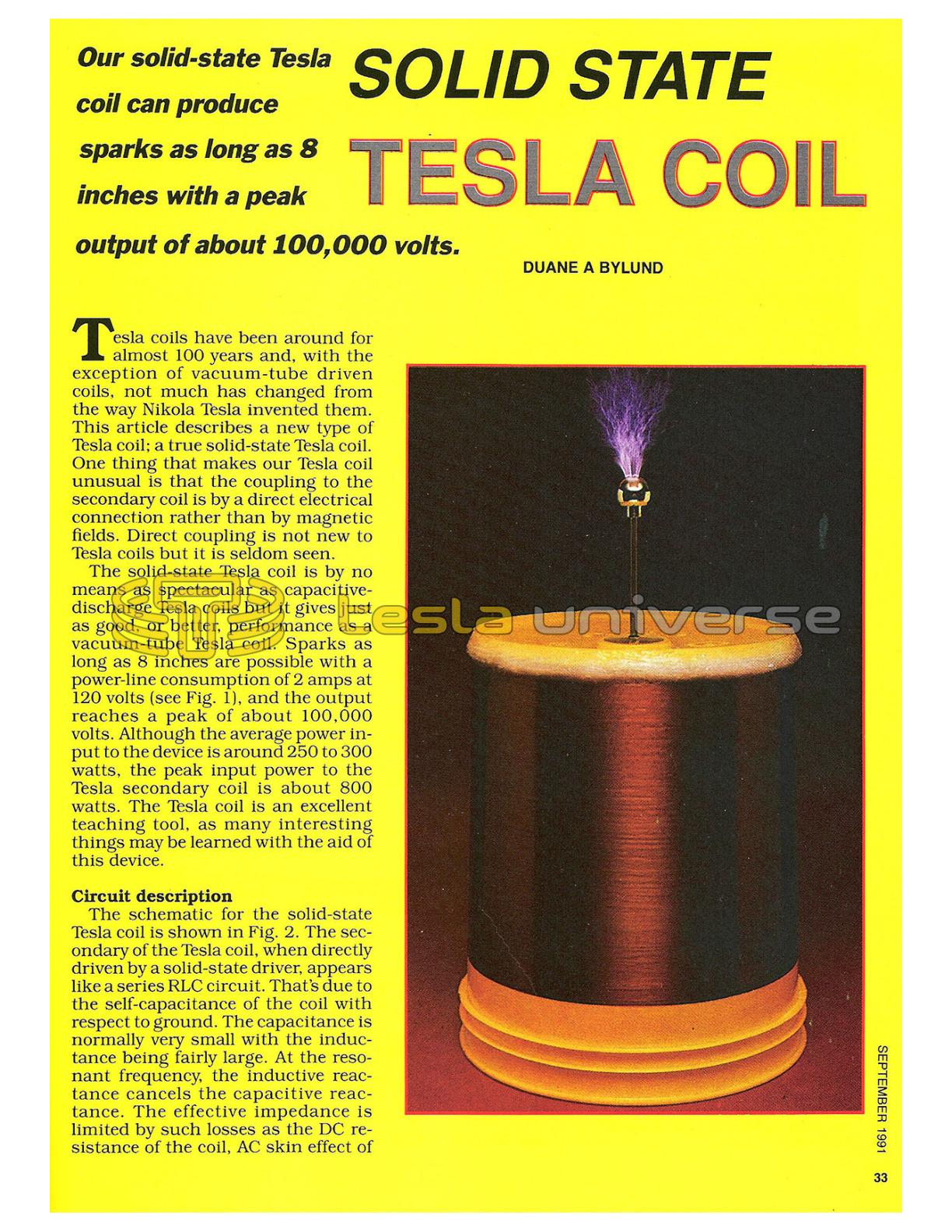
Our solid-state Tesla coil can produce sparks as long as 8 inches with a peak output of about 100,000 volts.
Tesla coils have been around for almost 100 years and, with the exception of vacuum-tube driven coils, not much has changed from the way Nikola Tesla invented them. This article describes a new type of Tesla coil; a true solid-state Tesla coil. One thing that makes our Tesla coil unusual is that the coupling to the secondary coil is by a direct electrical connection rather than by magnetic fields. Direct coupling is not new to Tesla coils but it is seldom seen.
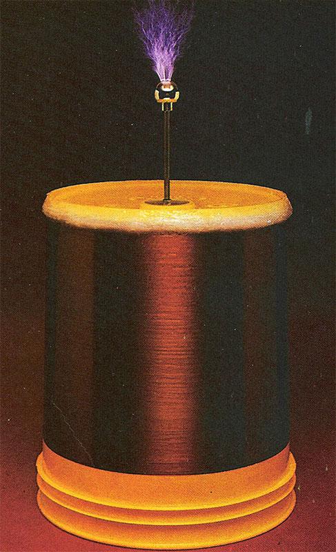
The solid-state Tesla coil is by no means as spectacular as capacitive-discharge Tesla coils but it gives just as good, or better, performance as a vacuum-tube Tesla coil. Sparks as long as 8 inches are possible with a power-line consumption of 2 amps at 120 volts (see Fig. 1), and the output reaches a peak of about 100,000 volts. Although the average power input to the device is around 250 to 300 watts, the peak input power to the Tesla secondary coil is about 800 watts. The Tesla coil is an excellent teaching tool, as many interesting things may be learned with the aid of this device.
Circuit Description
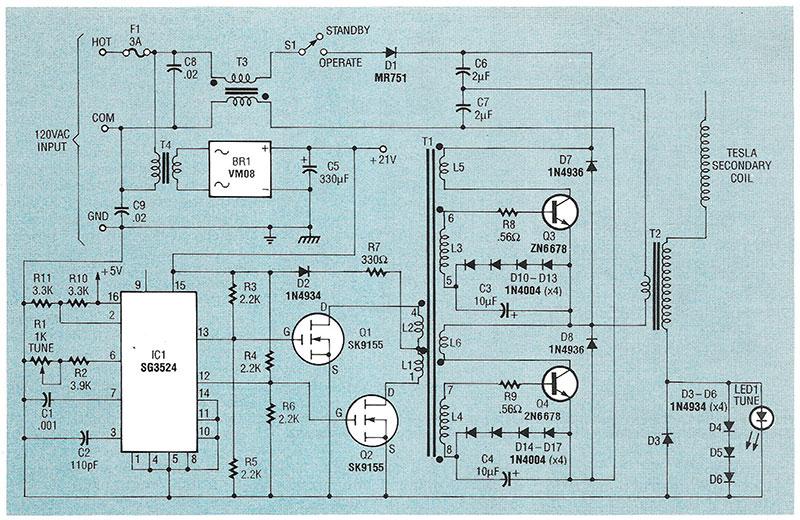
The schematic for the solid-state Tesla coil is shown in Fig. 2. The secondary of the Tesla coil, when directly driven by a solid-state driver, appears like a series RLC circuit. That's due to the self-capacitance of the coil with respect to ground. The capacitance is normally very small with the inductance being fairly large. At the resonant frequency, the inductive reactance cancels the capacitive reactance. The effective impedance is limited by such losses as the DC resistance of the coil, AC skin effect of the wire, eddy currents induced in nearby objects by the field of the coil, and so on.
Series RLC circuits have relatively low impedances when operated at the resonant frequency. The coil used in this project, when operated at its resonant frequency, looks like a 450-ohm resistive load to the solid-state driver. Series RLC circuits produce high voltages on the inductor and capacitor at the resonant frequency. The high voltage is due to a high current flowing through a high reactance (remember that the inductance is large and the capacitance is small, creating large reactances in each component at a given frequency). That is what produces the corona discharge at the end of the secondary coil.
Warning!! This article deals with and involves subject matter and the use of materials and substances that may be hazardous to health and life. Do not attempt to implement or use the information contained herein, unless you are experienced and skilled with respect to such subject matter, materials, and substances. Neither the publisher nor the author make any representation as for the completeness or accuracy of the information contained herein, and disclaim any liability for damages or injuries, whether caused by or arising from the lack of completeness, inaccuracies of the information, misrepresentations of the directions, misapplication of the information, or otherwise.
The heart of the driver is IC1, the SG3524 pulse-width modulator. The duty cycle is fixed at about 45% for best efficiency. The frequency is controlled by the resistance on pin 6 and the capacitance on pin 7. With the values shown, the frequency has a range from 200 to 240 kHz. A flip-flop inside the chip divides that by 2 so that the effective output of the driver has a range from 100 to 120 kHz.
The outputs on pins 12 and 13 are 180 degrees out of phase with each other, and drive the gates of MOSFET's Q1 and Q2, which, in turn, drive the primary of transformer T1. Transformer T1 drives the bases of switching-transistors Q3 and Q4. The components in the base circuitry are used to increase the switching speed of the transistors. Transistors Q3 and Q4 switch the line voltage across the primary of T2, which increases the voltage and drives the end of the secondary coil directly. Note that the line voltage delivered to T2 is halfwave rectified by D1. That is important to the operation of the Tesla coil because a pulsating voltage is needed to produce the best effects.
When the device is plugged into a wall receptacle it will be in its standby mode. That is, the 21-volt power supply will be operational and the FET's will be driving the primary of T1. The standby mode produces enough power to "tune" the driver to the coils resonant frequency before full power is applied. (Remember that the resonant frequency can be affected by nearby objects.) The current supplied to the secondary coil is indicated by LED1. Tuning is accomplished by adjusting the frequency via R1 and observing LED1. When resonance is achieved, the secondary coil will have a low impedance which will produce maximum current, lighting the LED. Diodes D3-D6 limit the forward and reverse voltages on LED1 when in the high-power mode. (Note that you must use an LED that lights at 1.5 volts - some LED's, including most green ones, need 2.1 volts or higher.)
When the device is switched into the operating mode (or the high-power mode), half-wave line-voltage pulses will be applied to the primary of T2. As the halfwave voltage increases, the current in the secondary coil increases and the energy stored in the inductance and capacitance of the secondary coil will increase. During this time there is no corona from the secondary coil (if the coil is constructed as shown in this article). Sometime before the half-wave line voltage reaches its peak, the corona will appear on the secondary coil, which will dissipate the stored energy very quickly. During the remainder of the half-wave line voltage, the coil will produce corona but the energy level will not be as great as the initial discharge. The coil will produce sixty individual corona discharges every second, although you'll see a continuous discharge.
Construction
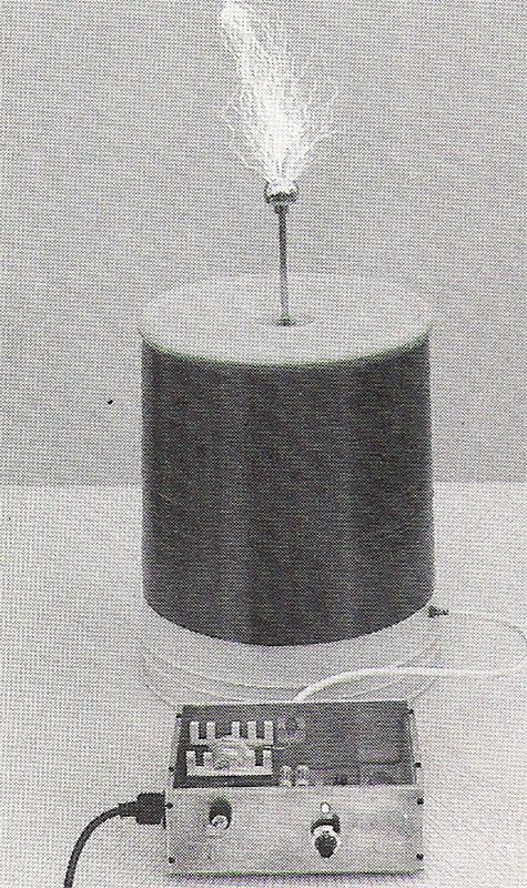
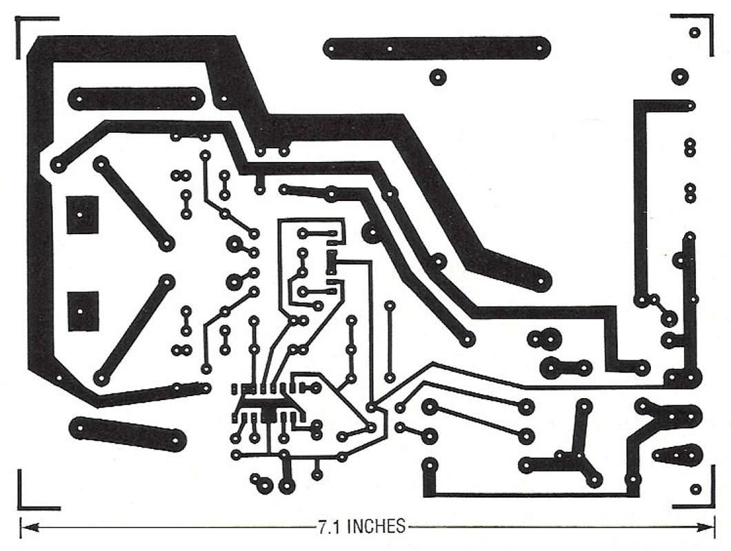
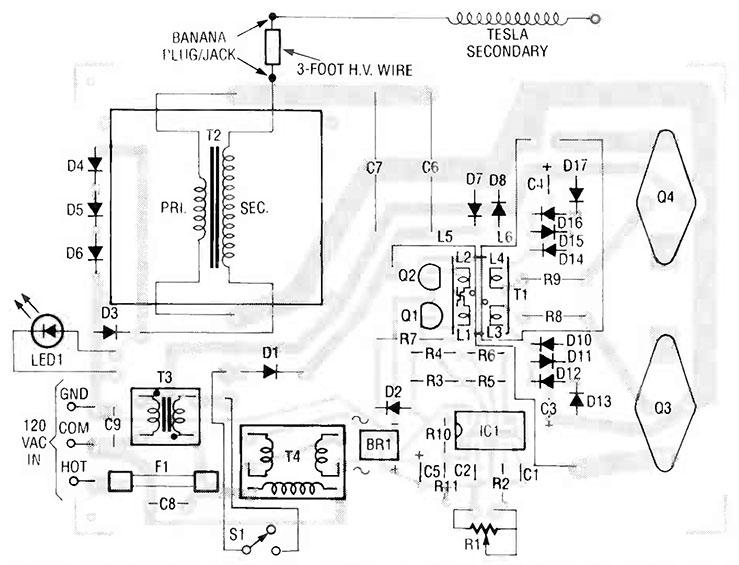
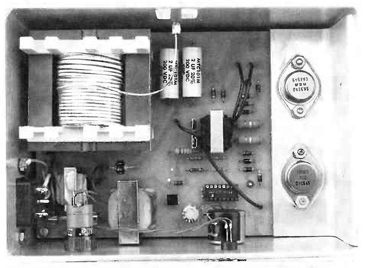
Most of the construction is fairly simple if the printed circuit board is used. A parts-placement diagram is shown in Fig. 3, and we've provided the foil pattern if you would like to etch your own board. Figure 4 shows the completed prototype board housed in its aluminum enclosure.
Parts List
All resistors are ¼-watt, 5%, unless otherwise indicated.
R1 - 1000 ohms, 10-turn potentiometer
R2 - 3900 ohms
R3, R4 - 2200 ohms, ½ watt
R5, R6 - 2200 ohms
R7 - 330 ohms, 1 watt
R8, R9 - 0.56 ohms, 2 watts, flameproof
R10, R11 - 3300 ohmsCapacitors
C1 - 0.001 uF, 50 volts, 5%, polyester
C2 - 110 pF, 50 volts, polyester
C3, C4 - 10 uF, 35 volts, tantalum
C5 - 330 uF, 35 volts, electrolytic
C6, C7 - 2 uF, 200 volts, nonpolar film-type
C8, C9 - 0.02 uF, 1000 volts, ceramic discSemiconductors
IC1 - SG3524 pulse-width modulator
D1 - MR751 diode
D2-D6 - 1N4934 diode
D7, D8 - 1N4936 diode
D9 - not used
D10-D17 - 1N4004 diode
Q1, Q2 - SK9155 power MOSFET
Q3, Q4 - 2N6678 or SK9140 NPN transistor
LED1 - red LED. See textOther components
F1 - 3-amp, 250-volt, fast-blow fuse
BR1 - VM08 bridge rectifier, Varo
T1 - hand-made transformer (the core is TDK # PC30EER25.5-Z and the bobbin is TDK # BEER-25.5-118CP)
T2 - hand-made transformer (the core is TDK # PC30EC70-Z and the bobbin is TDK # BEC-70-116)
T3 - hand-made transformer (the core is TDK # PC30EER25.5-Z and the bobbin is TDK # BEER-25.5-118CP)
T4 - 115VAC/15VAC center-tapped transformer (Triad F-132P)
S1 - SPST key switchMiscellaneous: enclosure, aluminum angle bracket, high-voltage wire (to connect main unit to Tesla secondary), 30-gauge magnet wire for Tesla secondary and L1 and L2, 24-gauge magnet wire for L3 and L4, 18-gauge stranded hook-up wire for L5 and L6,15-gauge magnet wire for T2 primary, 26-gauge hook-up wire for T2 secondary, 18-gauge magnet wire for both windings of T3, brass rod, discharge ball, hardware, AC linecord, etc.
Note: TDK ferrite cores and bobbins are available from MH&W International, 14 Leighton Place, Mahwah, NJ 07430, (201) 891-8800. The following items are available from Corona Coil, PO Box 474, Riverton, UT 84065:
- T1 - $15.00
- T2 - $38.00
- T3 - $12.00
- T4 - $14.00
- Tesla secondary coil - $50.00
- PC board - $15.00
- Aluminum angle bracket (heatsink and PC-board mount) - $5.00
A 124-page book by the author, Modern Tesla Coil Theory, is available for $16.
Please add $15 S&H for the Tesla secondary, and 10% S&H for all other items.
The most difficult item to construct will be the Tesla secondary coil, followed by T1 and T2. The secondary coil may take an hour or so to make if you prepare ahead of time. Preparation includes making some device that will easily rotate the coil form while winding the wire. The author used a small lathe and it took about 15 minutes of actual winding time and 30 minutes to get set up.
Do not deviate at all from the following parameters of the secondary coil! Any deviation will change the characteristics of the coil and it may not operate with the driver unless modifications in the driver are made. Any change in physical dimensions or wire size will alter the resonant frequency and effective impedance of the coil. Any change to the discharge electrode will effect the maximum energy obtainable.
The coil form for the secondary winding is a standard 5-gallon plastic container 10 inches in diameter at the bottom. 12 inches in diameter at the top, and 14 inches long. The bottom of the container becomes the top of the coil. To make winding easier you should drill a hole about an inch in diameter through the center of the bottom of the container. A similar hole should be drilled through a removable lid and then the complete coil form can be rotated easily on a dowel. Start the secondary winding 1 inch from the small-diameter end and close-wind 30-gauge magnet wire for a total length of 10 inches. It does not matter what direction the wire is wound in.
When winding the original coil for this article, shellac was used to lubricate the wire as it was wound and also to act as a sealant afterwards. It was difficult to wind the coil because the coil form was very slick and had a slight taper to it and, as a result, the wire kept slipping. It may be easier to spray the container with adhesive before winding the wire to make it stay in place. A couple of coats of shellac should be applied to the finished winding. You also must put 3 or 4 beads of silicone sealant around the end of the winding at the top of the coil to keep corona discharges away from the area. If corona discharges appear along the coil at the top it will limit the maximum energy and destroy the coil form.
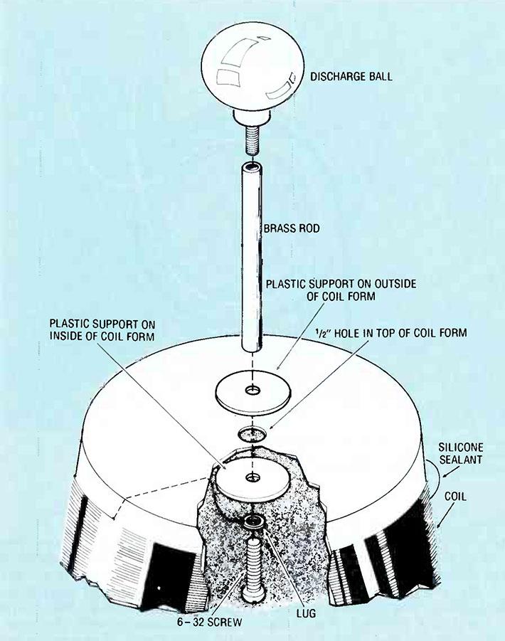
The discharge ball, or electrode, is a brass-plated metal doorknob, 1-inch in diameter, that can be found in hardware stores (see Fig. 5). The ball is mounted on a 4-inch brass rod; you can drill and tap the ends of the brass rod with a 6-32 tap (or whatever matches the threading on the doorknob) to make mounting easier. The brass rod is connected to the coil form by two pieces of plastic, one on each side of the coil form, over the ½-inch hole. A 6-32 screw passes through the pieces of plastic and into the brass rod to hold the assembly together. The wire is soldered to a lug held in place by the 6-32 screw.
A banana jack is used to make connections at the bottom of the coil. Locate the jack about 3/4-inch from the edge of the wire on the coil. Silicone should be used to insulate the connections between the magnet wire and the brass rod and banana jack. The finished coil, when built exactly as we've shown, will have a resonant frequency of about 110 kHz.
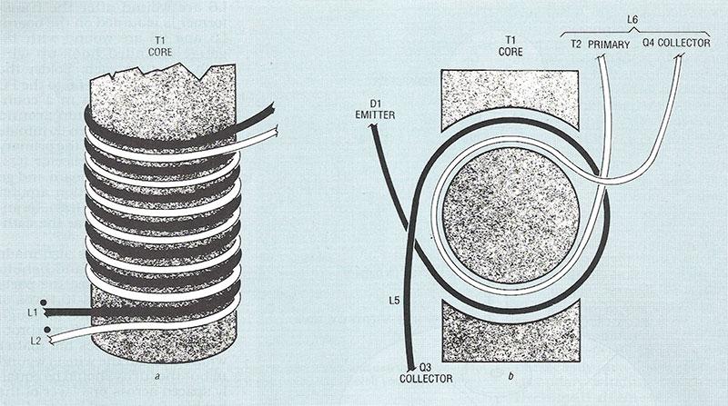
Transformer T1 is made with a ferrite core and bobbin from TDK (see the parts list). Coils L1 and L2 are wound first with 30-gauge magnet wire. 16 turns each, making one layer on the bobbin. The two windings are bifilar wound, as shown in Fig. 6-a: L1 starts on pin 3 and L2 starts on pin 4. Wind both in a counterclockwise direction while looking at the top of the bobbin. Terminate L1 on pin 1 and terminate L2 on pin 2. Put a layer of cellophane tape on top of the winding to insulate it from L3 and L4.
Coils L3 and L4 are made with 5 turns each of 24-gauge magnet wire and are also bifilar wound, on top of L1 and L2, and in the same direction. Coil L3 starts on pin 6 and L4 starts on pin 8. Terminate L3 on pin 5 and terminate L4 on pin 7. This completes the transformer until it is mounted on the PC board.
Put the two core halves through the bobbin and put tape around them to hold them in place. As shown in Fig. 6. L5 and L6 are wound after the transformer is mounted on the board; L5 and L6 are wound with 18-gauge stranded hook-up wire with one turn each. Solder the collector (Q4) end of L6 to the PC board. Go one turn in a counterclockwise direction around the core of T1 and then terminate the other end of L6 at the primary of T2. Solder the collector (Q3) end of L5 to the PC board and go in a clockwise direction around the core of T1 for one turn, terminating the winding at the cathode of D1.
Transformer T2 is also made from a ferrite core and bobbin from TDK (again, see the parts list). The primary is 10 turns of 15-gauge magnet wire, although a smaller gauge, say 18, can probably be used. It does not matter what direction the wire is wound in but the turns should be equally spaced across one layer of the bobbin. Put several layers of cellophane tape on top of the primary to insulate it from the secondary and to provide a smooth surface on which to wind the secondary. The secondary is made with 280 turns (the exact number is not critical) of 26-gauge hook-up wire. The direction is unimportant. You can use magnet wire if you desire but you should put cellophane tape between each layer. The low-voltage end of the secondary is the one that is the closest to the primary winding. When the windings are complete, put the core halves through the bobbin and hold them in place with tape wrapped around them.
Transformer T3 is made with the same core and bobbin as T1. Both windings are bifilar with 18-gauge magnet wire for as many turns as possible. The start of both windings are polarized as indicated by a dot in the schematic diagram (Fig. 2). The pins on the bobbin are not used and should therefore be cut off, and the 18-gauge wires are then soldered directly to the PC board as indicated.
An aluminum angle bracket is used when mounting switching-transistors Q3 and Q4. The bracket provides the physical support between the PC board and enclosure and also provides good heat sinking for the transistors. The transistors should be insulated from the aluminum; insulating hardware is normally included when you purchase the transistors. Use the PC board as a template for drilling holes for the transistors in the aluminum bracket. The angle bracket is mounted to the enclosure by drilling holes and taping them with a 6-32 tap. Thermal conductive compound is used between the transistors and angle bracket and between the angle bracket and the enclosure.
A banana jack is mounted in the back of the enclosure to make connections between the Tesla secondary coil and the high-voltage ferrite transformer. The output voltage from the ferrite transformer may reach 5000 volts peak with no load so it is wise to use extra insulation for the banana jack. Mount a piece of plastic, 1½-inch square, to the back of the enclosure over a 1-inch square hole, and mount the banana jack in the center of the plastic. That will space the banana jack at least ½-inch from the metal enclosure.
The prototype used a 10-turn potentiometer for R1 to make frequency adjustments easier and this allowed the use of a 10-turn dial to mark the frequency settings for different purposes. You can use a regular potentiometer but the 10-turn unit is superior.
An enclosure was fabricated out of ⅛-inch aluminum with a plexiglass top, but any metal enclosure would be suitable. Just be absolutely sure that you ground the metal enclosure.
Operation
Warning: The power output from the Tesla coil is dangerous! Make sure no one comes in contact with the output voltage directly from the driver. Make sure nobody tampers with the unit, and keep it out of reach of children. Make sure you use a key switch to turn power on and off to prevent someone from getting injured, and keep the key in a safe place.
Caution: All components on the secondary of T1 are not isolated from the power line. Use caution when measuring values in this area. You must isolate an oscilloscope from ground if measuring in this area. Make sure you use a three-prong power cord and that the case of the driver is well grounded. Also, make sure you plug the unit into a well-grounded electrical outlet.
Double check all wiring to make sure it is correct. Make sure the operate switch is in the standby position (line voltage disconnected from D1). Using a digital voltmeter isolated from ground, measure the voltage across C3 and C4. If everything is working correctly in the low-voltage circuitry, there should be about 2.5 volts across those capacitors. If that voltage is not present you should check the 21-volt power supply. Make sure that 5 volts is on pin 16 of IC1. If the oscillator is working correctly you should have about 3.6 volts on pin 6 of IC1.
Connect the Tesla secondary coil to the driver with a 3-foot insulated wire (it is a good idea to keep at least 3 feet from the secondary coil). You should always unplug the driver when you are making connections between the driver and secondary coil to be absolutely safe. The wire connecting the coil and driver carries a dangerous amount of power so be certain the wire is well insulated. In a dimly lit room you should be able to adjust the tune control to set the driver at the coil's resonant frequency. Observe the LED and watch for one place in the tuning control's adjustment where the LED glows brighter than anywhere else. Never apply full power to the driver unless you can obtain resonance first. Damage to the driver will most likely occur if resonance is not maintained.
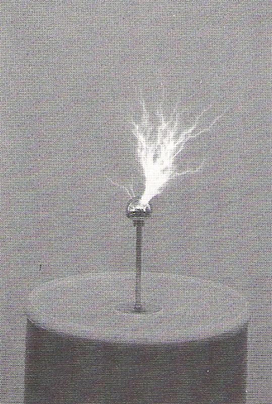
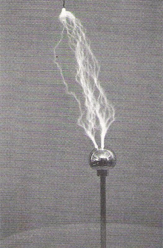
Once you obtain resonance you can switch to the full-power mode; the LED will glow very brightly. With no objects around the coil you should observe a snappy brush discharge 5 to 6 inches in length emanating from the discharge electrode (see Fig. 7). It might be somewhat louder than you would expect. Very slight adjustments in the tune control may improve the discharge. You should be able to get 7-inch streamers with a grounded electrode above the coil (see Fig. 8). Be aware that any change of the physical surroundings around the coil will change its resonant frequency and the tune control will need to be adjusted to maintain resonance. When operating the Tesla coil, be aware of the temperature of the enclosure where the aluminum angle bracket is mounted. Shut off the power if the area gets too warm. The prototype was operated for 2 full minutes, and you could just start to feel some warmth on the enclosure. However, you should operate the Tesla coil only for short periods of time.
Once you have a working unit you can start to experiment with different things. Try removing the discharge ball and use a point instead. Try changing the distance of the ball electrode from the coil. Try holding an incandescent lamp a short distance from the coil - but be very careful. Different lamps will produce different discharges.