Plans
Tesla Turbine - Part 3
Photos and drawings by Author
Bearing Cups

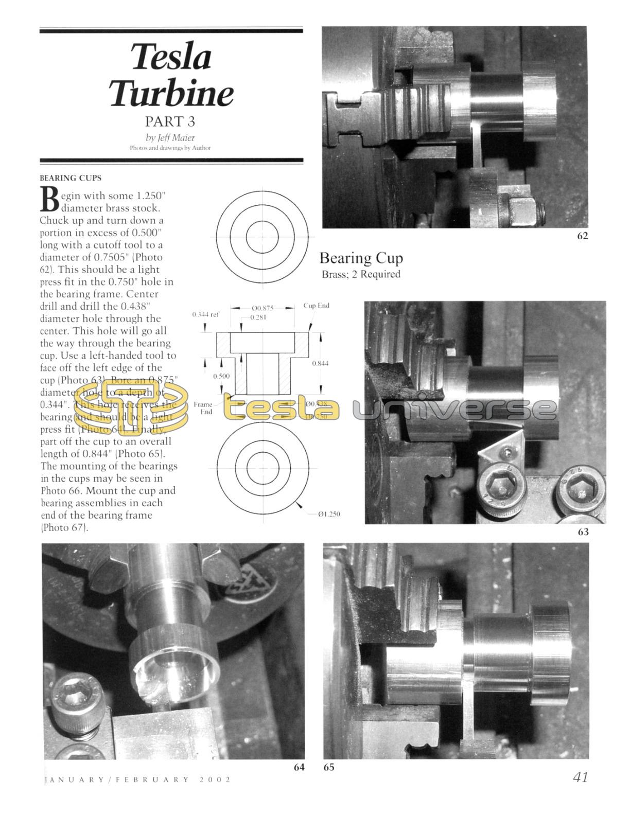
Begin with some 1.250" diameter brass stock. Chuck up and turn down a portion in excess of 0.500" long with a cutoff tool to a diameter of 0.7505" (Photo 62). This should be a light press fit in the 0.750" hole in the bearing frame. Center drill and drill the 0.438" diameter hole through the center. This hole will go all the way through the bearing cup. Use a left-handed tool to face off the left edge of the cup (Photo 63). Bore an 0.875" diameter hole to a depth of 0.344". This hole receives the bearing and should be a light press fit (Photo 64). Finally, part off the cup to an overall length of 0.844" (Photo 65). The mounting of the bearings in the cups may be seen in Photo 66. Mount the cup and bearing assemblies in each end of the bearing frame (Photo 67).


Shaft
The shaft is turned from 0.562" diameter steel stock. Begin with a piece approximately 7" long, face off and center drill each end. Mount the shaft between centers in the lathe. I prefer to use the four-jaw chuck as a means to clamp onto the shaft. Turn the short end down to 0.375" diameter for a length of 1.656".
This is the end toward the tailstock (Photo 68). Turn the last 0.750" down further to a diameter of 0.188". Using a cutoff tool, turn a short section at the headstock end down to 0.375". Also, use the cutoff tool to mark the approximate position of the transition between the 0.375" diameter portion and the central, 0.500" diameter portion of the shaft. This may be seen in Photo 69.


Next, use either a left-handed tool or the cutoff tool to turn this portion of the shaft down to a 0.375" diameter. As Photo 69 shows, I used the cutoff tool. With a left-handed tool, cut the final length of the central portion to 3.312" (Photo 70). At this point, the length of the 0.375" diameter portion of the shaft nearest the four-jaw chuck should be greater than the required 1.781". Switching back to the right-handed tool, turn the central portion of the shaft down to 0.500" diameter (Photo 71). While I didn't do this now, it would be wise to turn down a 0.250" length to a diameter of 0.250" at the headstock end. This would ensure that the entire shaft is done in one turning. Release the tailstock and part off (Photo 72).
Transfer the shaft to the mill. Cut the tachometer wheel setscrew flat with a 0.156" end mill (Photo 73). Cut two setscrew flats 90° apart on the 0.188" diameter portion of the shaft (Photos 74 and 75). Finally, thread the 0.250" end 1/4-28.


Runner Hub
Begin with a length of 1.25" diameter brass rod. Chuck up in the lathe and turn down 0.250" to a diameter of 0.375" (Photo 76). Transfer to the mill, clamp in a V-block and center up as shown in Photo 77. Drill the four No. 29 holes (Photo 78) and tap 8-32. Center up again and drill the center No. 3 hole (Photo 79). Tap this hole 1/4-28. Move back to the lathe and clamp as seen in Photo 80. Set the compound rest to 60° and cut the cone shape. Be sure to leave the 0.031" flat edge shown in the drawing.


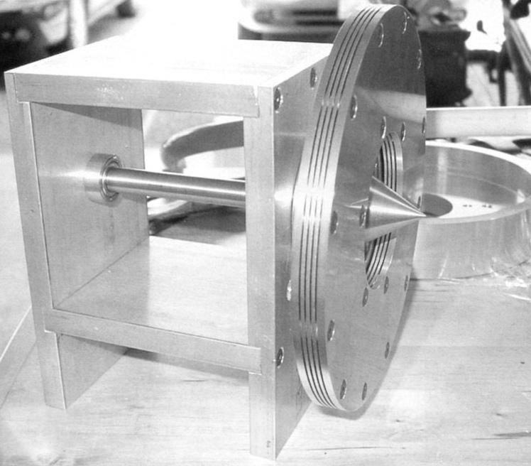
Photo 81 shows the shaft, runner hub, and runner shaft hub. The runner disk assembly is held between the two hubs by four 8-32 screws, and the shaft screws into the 1/4-28 hole in the center of the runner hub.
I found it necessary to perform the operation in Photo 82. Chuck up the shaft, with the hub screwed on. Take a facing cut on the flat surface of the hub. This will insure that the runner disk assembly is perpendicular to the shaft, preventing wobble.


Initial Assembly
Photo 83 shows the initial assembly of the bearing frame, shaft, runner hubs, and runner disk assembly. Make certain that the shaft turns freely and that it is a light press fit into the bearings. Also, check the runner disk assembly for runout and wobble. If the shaft is tight, you may need to shorten the central, 0.500" diameter portion a little bit.


Tachometer Sensor Block
Start this piece with a block of aluminum 1.500" x 1.500" x 1.125". Drill a 0.750" diameter hole to a depth of 0.750", as shown in the drawing. Next, drill the four No. 43 holes, located from the 0.750" hole (Photo 84). Tap these holes 4-40. Turn the block over and drill the two No. 43 holes to a depth of 0.312". Tap 4-40. Start the 0.250" slot by drilling two 0.234" holes spaced 0.250" apart (Photo 85). Finish off the slot with a 0.250" end mill (Photo 86). Photo 87 shows the mounting of the optical sensor. Solder four wires to the four terminals on the sensor and use heat shrink to insulate them. Pass the wires through the sensor block as shown. Next, pass the wires through the top plate of the bearing frame. Crimp the connector pins on and insert the pins into the connector (Photo 88). Finally, tuck the wires into the space inside the sensor block and attach the block to the bearing frame top plate with four 4-40 screws through the mounting holes in the connector (Photo 89).


Tachometer Sensor Wheel
Chuck up some 2" diameter aluminum stock in the lathe. Using a cutoff tool, turn down a section approximately 1" long to a diameter of 0.750". Turn down the outer section to 1.500" diameter (Photo 90). Use a left-handed tool to face off the inner edge (Photo 91), then face off the outer edge to a thickness of 0.063".
Center drill and drill the central 0.500" diameter hole (Photo 92). Next we'll transfer to the rotary table. Center the table under the spindle (Photo 93). Clamp the sensor wheel down and center up as seen in Photo 94. Using a 0.125" end mill, cut six slots to a depth of 0.312" spaced 60° apart (Photo 95). Transfer back to the lathe and part the sensor wheel off (Photo 96). Transfer to the mill again, clamp in the vise, and drill the No. 43 hole for the setscrew (Photo 97). Tap 4-40. Mount the sensor wheel on the shaft. Line it up in the optical sensor as well as aligning the setscrew hole with the flat on the shaft. Tighten down the setscrew (Photo 98). When the shaft spins, it will produce six pulses per revolution. This results in a signal with a frequency one-tenth of the RPM; that is, a speed of 1,000 rpm will produce a 100Hz signal.
We will work on the cover and nozzle next time.