Plans
Tesla's Transformer
Attention: Intended for those who understand electronics well and all dangers from high voltage currents!
The Tesla transformer, which is in fact a converter of low-frequency currents into high-frequency currents, has always attracted attention, from the moment of its origin somewhere in 1891, up to today. Soon after the discovery of the Tesla transformer this device became an integral part of every physics laboratory.
The Tesla transformer can be made in various ways, but resonant transformer and spark gap are always present in essence, through which the capacitor of the primary oscillatory circuit is discharged.
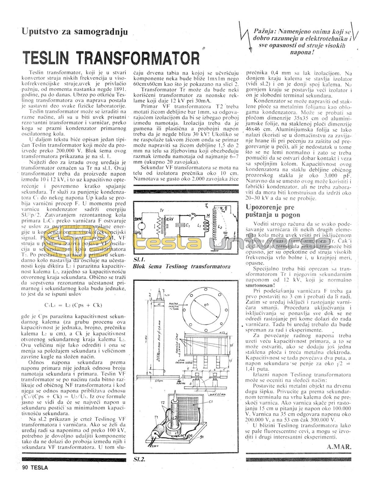
In the following text one typical Tesla transformer will be described which can produce over 200,000 V. The block diagram of this transformer is shown on sl. 1.
The hardest part for the construction of this device is the transformer marked with Tr on sl.1. This transformer must produce a voltage between 10 and 12 kV, and that with capacitive load and occasional short-circuiting of the primary L1 through the spark gap F. At the moment before the spark gap the capacitor contains energy ½ C Up². By closing the resonant circuit of the primary L1:C1 through the spark gap F the condition is achieved for converting the accumulated energy in the capacitor into a high-frequency signal. Through the coupling coefficient M, the HF current in the primary causes the appearance of HF oscillations in the secondary coil of the transformer T2. After the cessation of the spark in the primary the secondary circuit continues to oscillate at the frequency dictated by L2 and the parasitic capacitance of the open end of the secondary. Usually it is required that the natural resonant frequency of the primary and secondary coils be the same, that is to fulfill the condition
C1 L1 = L2 (Cps + Ck)
where Cps is the parasitic capacitance of the secondary coil (for rough estimation this capacitance is numerically equal to the diameter of the coil L2 in cm), and Ck is the capacitance of the open secondary end of the coil L2. This quantity is not easy to determine and it changes with the position of the secondary and the size of the terminating sphere in a complex way.

The ratio of the secondary voltage to the primary voltage is not equal to the ratio of the number of turns of the secondary and primary. The Tesla VF transformer differs essentially in its mode of operation from an ordinary NF transformer and in it the voltage ratio approaches the ratio √(C1/(Cps + Ck)) = U2/U1. From this formula it is clearly seen that the highest voltage in the secondary will be achieved with the minimal capacitance of the secondary.
On sl.2 is shown a drawing of the Tesla VF transformer and the spark gap. If one wants the device to operate with voltages over 100 kV, it is necessary to sufficiently separate the components so that there is no breakdown between them and the secondary of the VF transformer. In that case the wooden board on which the components are fixed should be closer to 1m x 1m than 60cm x 60cm as shown in picture 2.
Transformer Tr can be some purchased transformer for neon signs which gives 12 kV at 30mA.
Primary of the VF transformer T2 must be wound with wire of thickness at least 1mm, with appropriate insulation to avoid breakdown between windings. The insulation must be rubber or plastic and the test voltage should be somewhere near 30 kV! If such wire is not available then the primary can be made with wire of thickness 1.5 to 2 mm on the body with grooves which ensure a gap between windings of at least 6-7 mm (total 20 turns).

Secondary of the VF transformer is wound on a body of insulator with diameter about 10 cm. It is wound densely with about 2,000 turns of wire of 0.4 mm diameter with lacquer insulation. On the lower edge of the coil an insulator is placed (see sl.2) and on it the lower connection of the coil. On the upper edge a larger insulator is placed and on it the free terminal of the secondary.
The capacitor can be made from glass plates with metal foils as electrodes. One can try with a plate capacitor of dimensions 35x35 cm of aluminum foil, on a glass plate of dimensions 46x46 cm. Aluminum foil is easy to find (it is used in households for wrapping food or for baking), but the disadvantage is that it has small unevennesses and therefore it is necessary to ensure good contact and connection with molten lead. The capacitance of this capacitor made on glass of ordinary window glass thickness is about 3,000 pF. Naturally a factory-made capacitor can be used instead, but it must not be forgotten that it has to be constructed to withstand about 20-30 kV without breaking down.
Warning before putting into operation
Pay strict attention that every adjustment of the spark gap F and some other elements of the circuit must always be performed with the primary voltage of the transformer Tr disconnected. Even touching the secondary terminal can be dangerous, because the effects of high-frequency currents are very painful and, in extreme measure, dangerous.
Special caution must be exercised with the transformer Tr and its secondary voltage of about 12 kV, which is normally lethal!
When adjusting the spark gap F it should first be set at 3 cm and tested whether it works. Then the device is switched off and the spark gap distance is reduced. The procedure of switching on and off is repeated until the distance at which the spark gap operates is determined. Then the device should be ready for operation and experiments.
For increasing the working voltage a larger primary capacitance should be used, and this can be realized if another glass plate and a third metal electrode are added. The capacitance then increases two times, and the secondary voltage rises by about √2 = 1.41 times.
The output voltage of the Tesla transformer can be estimated in the following way:
Place some metal object on a long wooden stick. Bring it near the secondary terminal on the top of the coil while the spark gap is not sparking. If the spark does not jump at 15 cm then the voltage is about 100,000 V. The spark at 35 cm corresponds to about 200,000 V, and at 53 cm about 300,000 V.
In the vicinity of the Tesla transformer fluorescent tubes light up easily, and other interesting experiments can be performed.
A.MAR.