
TCBA Volume 5 - Issue 1
Page 14 of 18
Build VHV Supply
10,000 Volts from Commonly Available Components
By Paul H. Fuge
There still exists a real need for very-high-voltage power supplies even in this era of low-voltage solid-state electronics - especially in the area of experimenting. A casual look around the various school science fairs will reveal that interest is still high for such projects as air ionizers, Van de Graaff generators, Tesla coils and the like. (One practical use for a VHV supply was given in “The Not Altogether Forgotten Electret” in the March 1969 Popular Electronics.)
In most cases, the VHV power supply is required to deliver currents on the order of only a few microamperes. So, to meet this requirement with maximum economy, the VHV Supply described here consists of an SCR, a capacitor, a common automobile spark coil, and a simple triggering circuit. Operated from any 117-volt a.c. house line, the supply produces an output on the order of 10,000 volts which will jump a 3/8" spark gap and melt an electrode made of solder.
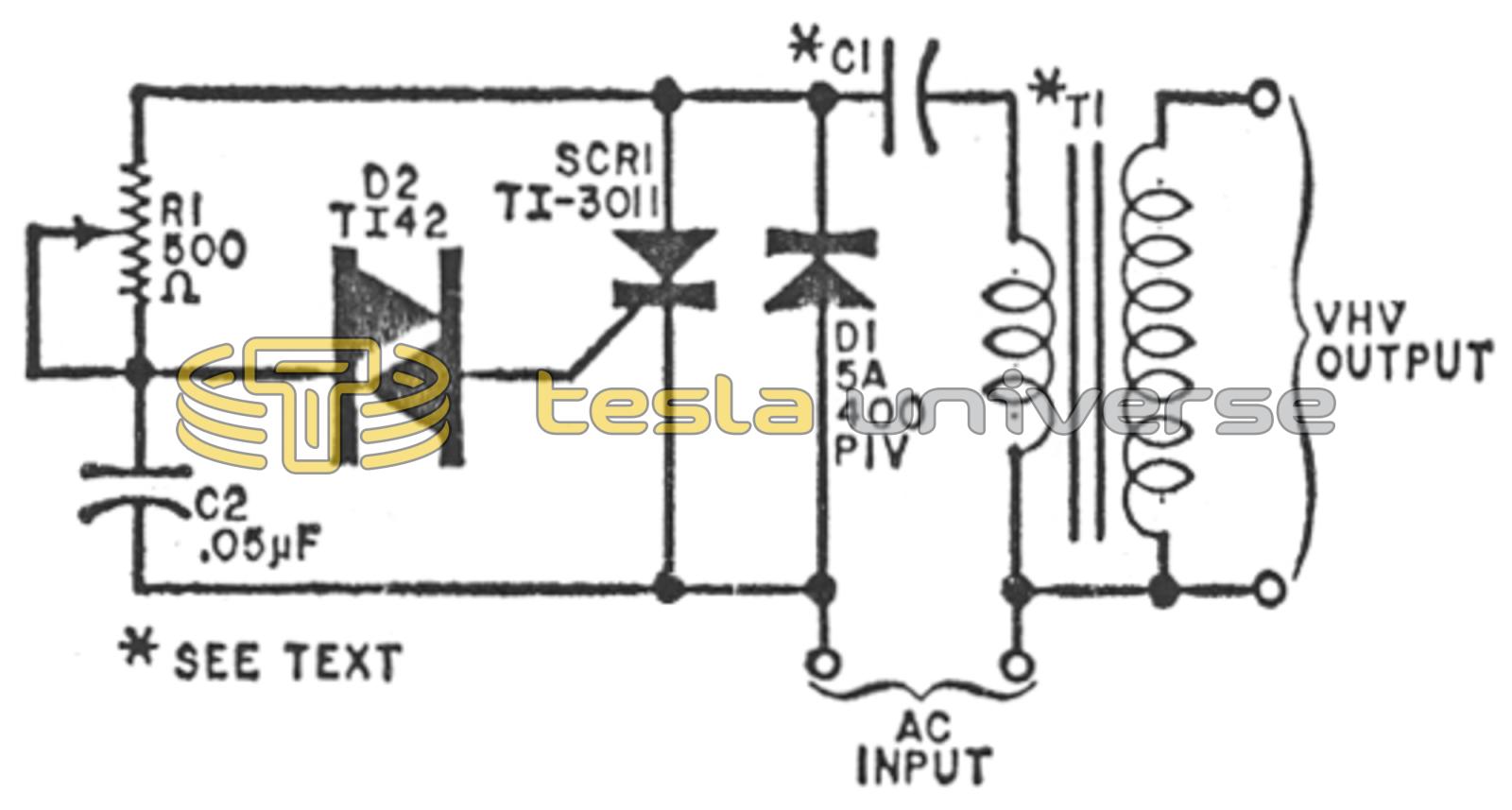
How It Works. Referring to the schematic diagram, when line power is applied to the circuit, D1 conducts only when it is forward biased, allowing C1 to charge up. Then, when D1 becomes reverse biased, C2 charges up through R1. At some point during the charge cycle, the potential across C2 reaches and exceeds the breakover voltage of trigger diode D2. When this happens, D2 conducts and delivers a triggering pulse to the gate of SCR1; turning it on.
The instant SCR1 fires, it forms a series circuit with C1 and the primary of spark coil T1 across the power line. As a result, the charge on C1 rapidly discharges through the low-resistance T1 primary, inducing a much higher voltage across the secondary.
Then when D1 again becomes forward biased on the next cycle of the applied a.c., SCR1 cuts off, and the charge-discharge cycle repeats itself until the a.c. power is disconnected.
While the output of the VHV Supply is a.c., it can easily be converted to d.c. by installing a high-voltage TV (silicon) rectifier and filter capacitor across the high-voltage secondary of T1. However, if you do this, be careful to limit the value of C1 to a small figure to prevent damaging the rectifier by high-current spikes when C1 discharges. If an a.c. output is required, the value of C1 can be anywhere between 2 and 100 µF, although the larger values will draw more current.
Construction. Parts location and orientation are left to your discretion when assembling the VHV Supply. However, since potentials on the order of 10,000 volts are developed by the supply, fully encapsulate all connections in a silicone potting compound after soldering. Then, for added protection, mount the entire circuit inside a perforated steel or aluminum cabinet.
When the supply is fully assembled, you can adjust the setting of R1 for maximum output power. Then, if desired, the optimum setting of the potentiometer can be measured and a fixed 1/2-watt resistor substituted for it in the circuit.
Finally, if you wish to vary the output voltage above or below the designed 10,000-volt level, you can use an adjustable auto-transformer between the a.c. line and input of the supply.
There appeared in TCBA NEWS, Volume 4 #4 a request for a solid state circuit for energizing a Tesla coil. The above was sent in by member R.S. Hedin of Minneapolis.