TCBA Volume 8 - Issue 1
Page 7 of 18
Fun with your Broadcast Radio Set
(continued)
The handles may be made from two pieces of metal pipe about 6 inches long. Drill a hole through the end of each and insert a bolt and nut for securing the wire to the pipe; or wrap the wire around the pipe and solder it in place. If metal pipe or rod cannot be conveniently obtained, two pieces of broom stick, around which tin foil is glued, will do the trick. It is better to twist the wire around the tin foil in this case, to insure a good contact.
The operation of the unit depends on the blocking effect of the condenser, which passes the alternating-current “signals,” but does not allow the direct current (“B” voltage) to get by. In this way, only the music passes through the body of the “subject”; and the intensity of the shock can be controlled by turning the volume-control of the set. The hardest shocks are felt when a powerful station is tuned in and the volume-control is “all the way on.” The experiment should be begun with the volume-control off; advance it slowly.
If a set has a “push-pull” amplifier (two power tubes) a special unit should be used, as shown in Figs. 1 and 3; it comprises a potentiometer, a small box, four binding posts and two metallic handles.
The potentiometer is mounted in the box with two pairs of binding posts on either side - one pair for connecting to the set and the other for the handles (Fig. 3). The two outer terminals on the potentiometer are secured to the binding posts designated “to set.” The central terminal of the potentiometer connects to one of the other pair of binding posts marked “to metallic handles” and the remaining terminal of the latter pair is wired to one of the “set” terminals.
In this case, the potentiometer serves to control the strength of the shock. The unit is connected differently from the first type. As it is particularly suited to push-pull sets, a wire may be twisted around each of the power tube plate prongs, or perhaps a more convenient method is to solder leads to the speaker cable. In the majority of push-pull receivers, a five-wire cable connects the speaker to the receiver chassis. Two of these wires are heavy and three are thin. The heavy ones carry the magnetizing current for the “field coil” of the speaker. The others carry the signals. Of these three, two are usually colored red, while the remaining one is a different color. The two red leads are the ones of interest to us now. The wires from the shocking unit are soldered to these red leads (which connect to each side of the speaker input transformer), either at the speaker cable plug or directly in the speaker, whichever is most convenient. The two other terminals of the Shocking Box are connected to the metallic handles.
It is well to add a word or two about the use of the Shocking Unit at this time. Modern receivers with their extremely high amplification build up signal currents to quite high levels - so high that the experimenters who build these devices must be careful not to increase the current too much, or a possible injury to the “subject” may result. Also, it is necessary to follow the wiring instructions carefully, so that the direct plate voltage does not pass through the “subject's” body. Modern sets employ plate voltages of 200 to 600 volts, which will be dangerous if direct contact is made. First, try the shocking current with the control set “all the way down.” Then slowly increase the current to the highest level you can stand - mark this point on the control and do not exceed it. Do not administer shocks to a person of weak heart.
The “Radio Dancers”
• THE speaker of a radio set, particularly the dynamic type with “free-edge” cone, has an appreciable mechanical movement when connected to a set that is playing. The coil or armature moves back and forth with a force that can be used to make mechanical toys and novelties function.
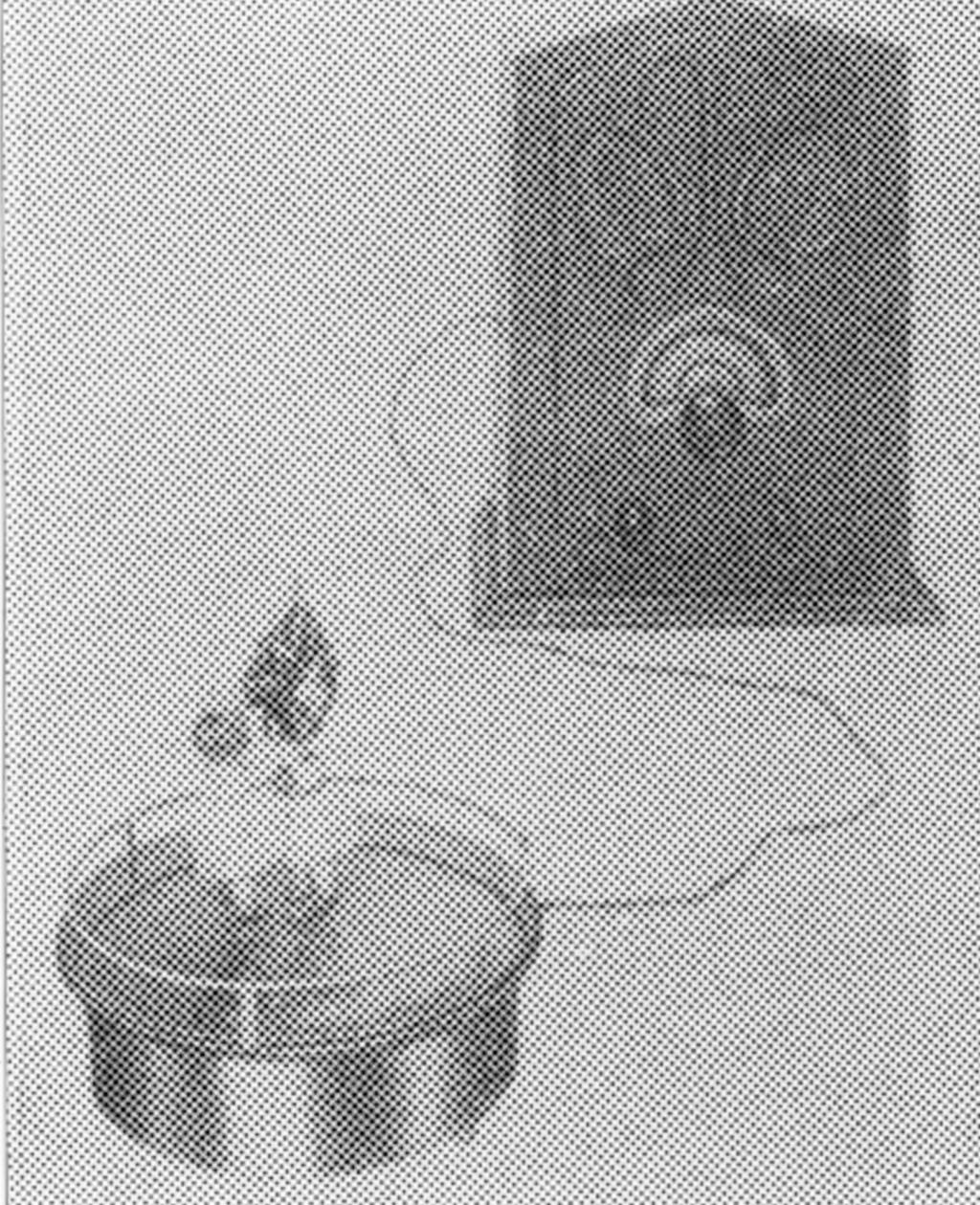
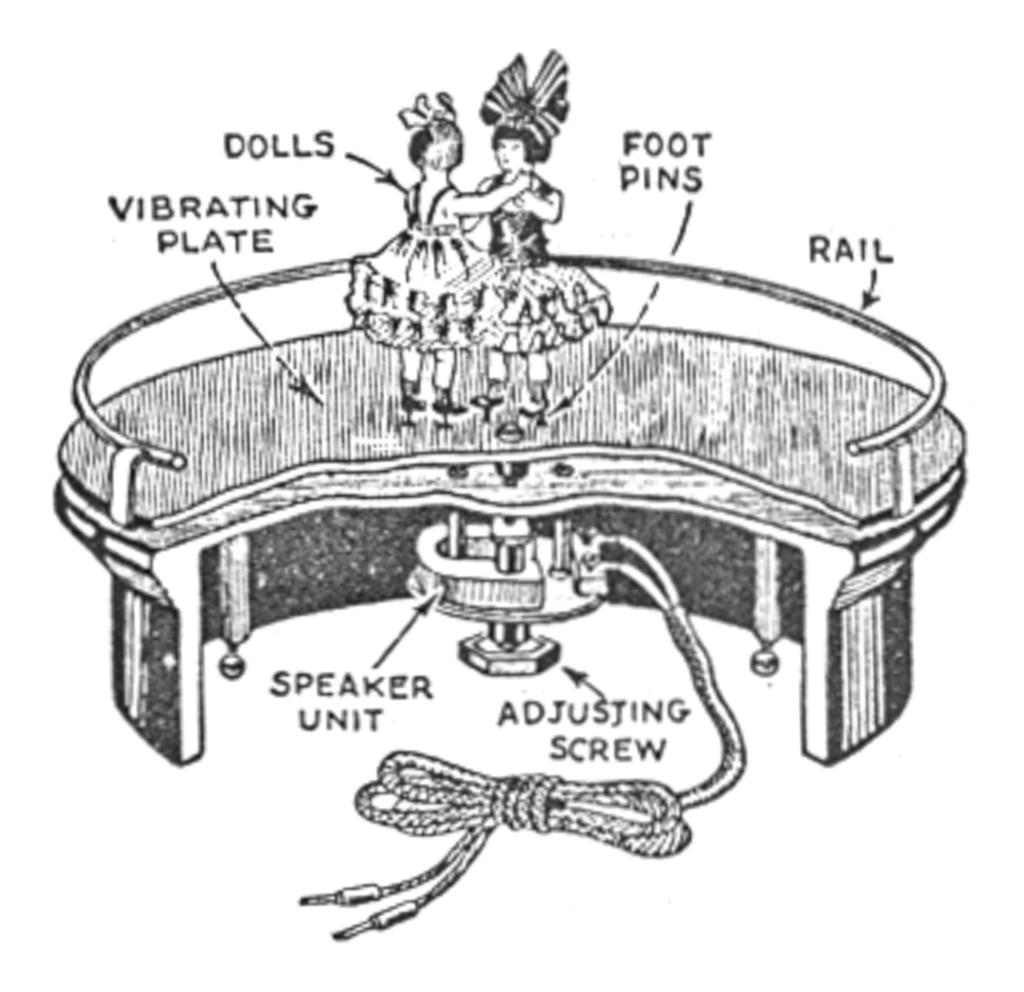
The “Radio Dancers,” suggested and published as far back as 1925 by the Editor of this magazine, and made commercially in Germany some time ago, affords a very good example. As shown in the illustrations, it is a little device suitable for the entertainment of children, the decoration of window displays, etc. The principle of the apparatus is very simple; it is simply a loud speaker, to be plugged into a radio set. The cross-sectional view (Fig. 5) shows all the essential parts. The box, of bakelite composition, has attached to it a thin sheet of bakelite, hard rubber or veneer, which is at once the diaphragm of the speaker and the dolls' dancing floor, and is operated by a standard speaker unit. The railing keeps the little dancers from falling off; the set-screws enable the floor to be leveled. This is important; as otherwise the dancers will travel to the lowest point of the edge and remain there.


