Nikola Tesla Articles
Mr. Tesla's Personal Exhibit at the World's Fair
While the exhibits of firms engaged in the manufacture of electrical apparatus of every description, at the Fair, afforded the visitor ample opportunity for gaining an excellent knowledge of the state of the art, there were also numbers of exhibits which brought out into strong relief the work of the individual inventor, which lies at the foundation of much, if not all, of our present achievement. Prominent among such personal exhibits was that of Mr. Nikola Tesla, whose apparatus occupied part of the space of the Westinghouse Company.
This apparatus represents the results of work and thought covering a period of ten years. It embraces a large number of different alternating motors and Mr. Tesla's earlier high frequency apparatus. The motor exhibit consisted of a variety of fields and armatures for two, three and multiphase circuits, and gave a fair idea of the gradual evolution of the fundamental idea of the rotating magnetic field. The high frequency exhibit included Mr. Tesla's earlier machines and disruptive discharge coils and high frequency transformers, which he used in his investigations and some of which are referred to in his published papers.
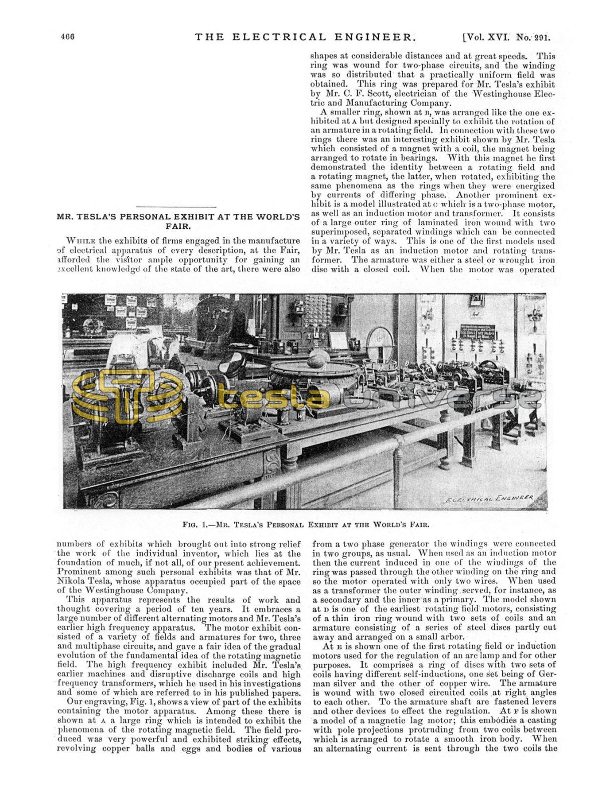
Our engraving, Fig. 1, shows a view of part of the exhibits containing the motor apparatus. Among these there is shown at A a large ring which is intended to exhibit the phenomena of the rotating magnetic field. The field produced was very powerful and exhibited striking effects, revolving copper balls and eggs and bodies of various shapes at considerable distances and at great speeds. This ring was wound for two-phase circuits, and the winding was so distributed that a practically uniform field was obtained. This ring was prepared for Mr. Tesla's exhibit by Mr. C. F. Scott, electrician of the Westinghouse Electric and Manufacturing Company.
A smaller ring, shown at B, was arranged like the one exhibited at A but designed specially to exhibit the rotation of an armature in a rotating field. In connection with these two rings there was an interesting exhibit shown by Mr. Tesla which consisted of a magnet with a coil, the magnet being arranged to rotate in bearings. With this magnet he first demonstrated the identity between a rotating field and a rotating magnet, the latter, when rotated, exhibiting the same phenomena as the rings when they were energized by currents of differing phase. Another prominent exhibit is a model illustrated at C which is a two-phase motor, as well as an induction motor and transformer. It consists of a large outer ring of laminated iron wound with two superimposed, separated windings which can be connected in a variety of ways. This is one of the first models used by Mr. Tesla as an induction motor and rotating transformer. The armature was either a steel or wrought iron disc with a closed coil. When the motor was operated from a two phase generator the windings were connected in two groups, as usual. When used as an induction motor then the current induced in one of the windings of the ring was passed through the other winding on the ring and so the motor operated with only two wires. When used as a transformer the outer winding served, for instance, as a secondary and the inner as a primary. The model shown at D is one of the earliest rotating field motors, consisting of a thin iron ring wound with two sets of coils and an armature consisting of a series of steel discs partly cut away and arranged on a small arbor.
At E is shown one of the first rotating field or induction motors used for the regulation of an arc lamp and for other purposes. It comprises a ring of discs with two sets of coils having different self-inductions, one set being of German silver and the other of copper wire. The armature is wound with two closed circuited coils at right angles to each other. To the armature shaft are fastened levers and other devices to effect the regulation. At F is shown a model of a magnetic lag motor; this embodies a casting with pole projections protruding from two coils between which is arranged to rotate a smooth iron body. When an alternating current is sent through the two coils the pole projections of the field and armature within it are similarly magnetized, and upon the cessation or reversal of the current the armature and field repel each other and rotation is produced in this way. Another interesting exhibit, shown at G, is an early model of a two field motor energized by currents of different phase. There are two independent fields of laminated iron joined by brass bolts; in each field is mounted an armature, both armatures being on the same shaft. The armatures were originally so arranged as to be placed in any position relatively to each other and the fields also were arranged to be connected in a number of ways. The motor has served for the exhibition of a number of features among other things, it has been used as a dynamo for the production of currents of any frequency between wide limits. In this case the field, instead of being energized by direct current was energized by currents differing in phase, which produced a rotation of the field; the armature was then rotated in the same or in opposite direction to the movement of the field and so any number of alternations of the currents induced in the armature, from a small to a high number, determined by the frequency of the energizing field coils and the speed of the armature, was obtained.
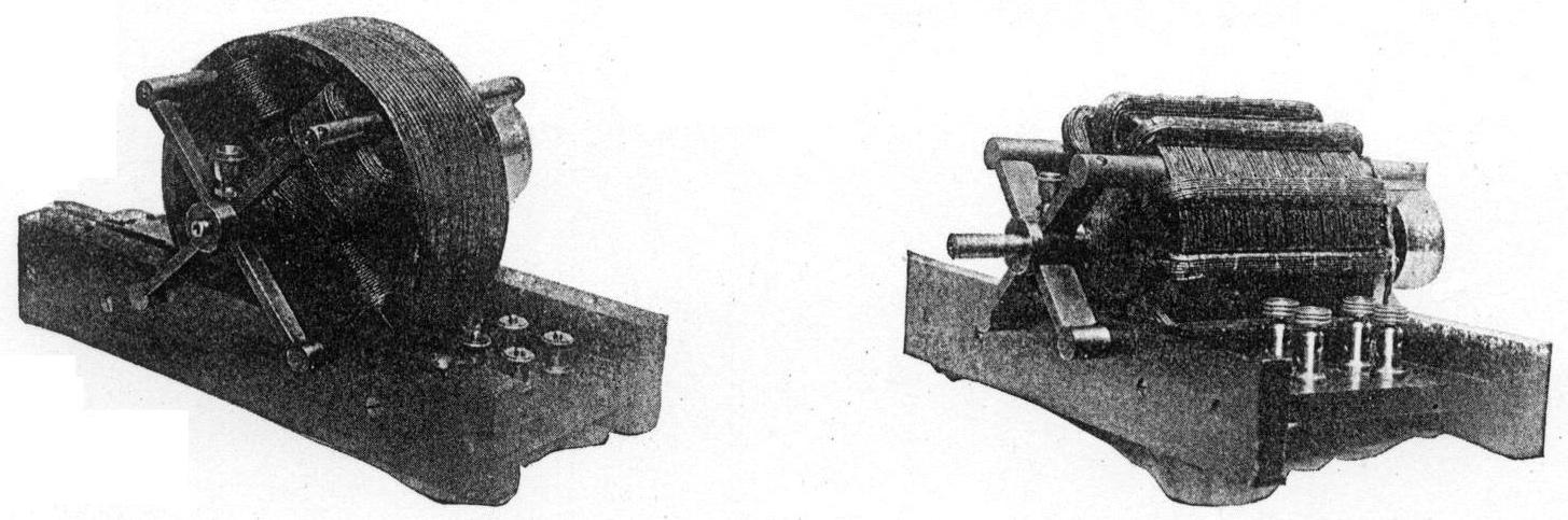
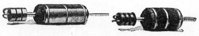
The models H, I, J, represent a variety of rotating field synchronous motors which are of special value in long distance transmission work. The principle embodied in these motors was enunciated by Mr. Tesla in his lecture before the American Institute of Electrical Engineers, in May, 1888. It involves the production of the rotating field in one of the elements of the motor by currents differing in phase and energizing the other element by direct currents. The armatures are of the two and three phase type. K is a model of a motor shown in an enlarged view in Fig. 2. This machine together with that shown in Fig. 3 were models exhibited at the same lecture, in May, 1888. They were the first rotating field motors which were independently tested, having for that purpose been placed in the hands of Prof. Anthony in the winter of 1887-88. From these tests it was shown that the efficiency and output of these motors was quite satisfactory in every respect.
It was intended to exhibit the model shown in Fig. 3 but it was unavailable for that purpose owing to the fact that it was some time ago handed over to the care of Prof. Ayrton in England. This model was originally provided with twelve independent coils; this number, as Mr. Tesla pointed out in his first lecture, being divisible by two and three, was selected in order to make various connections for 2 and 3-phase operations, and during Mr. Tesla's experiments was used in many ways with from 2 to 6 phases.

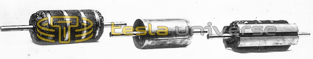
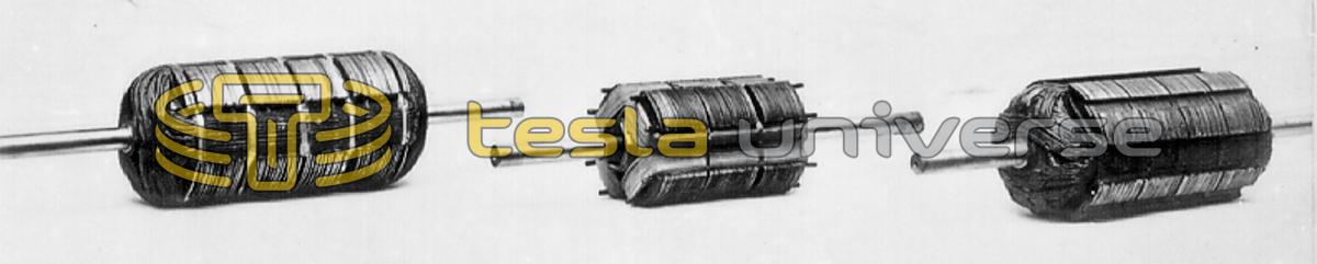
The model, Fig. 2, consists of a magnetic frame of laminated iron with four polar projections between which an armature is supported on brass bolts passing through the frame. A great variety of armatures was used in connection with these two and other fields. Some of the armatures are shown in front on the table, Fig. 1, and several are also shown enlarged in Figs, 4 to 14. An interesting exhibit is that shown at L, Fig. 1. This is an armature of hardened steel which was used in a demonstration before the Society of Arts in Boston, by Prof. Anthony. Another curious exhibit is shown enlarged in Fig. 5. This consists of thick discs of wrought iron placed lengthwise, with a mass of copper cast around them. The discs were arranged longitudinally to afford an easier starting by reason of the induced current formed in the iron discs, which differed in phase from those in the copper. This armature would start with a single circuit and run in synchronism, and represents one of the earliest types of such an armature. Fig. 9 is another striking exhibit. This is one of the earliest types of an armature with holes beneath the periphery, in which copper conductors are embedded. The armature has eight closed circuits and was used in many different ways. Fig. 8 is a type of synchronous armature consisting of a block of soft steel wound with a coil closed upon itself. This armature was used in connection with the field shown in Fig. 2 and gave excellent results.
Fig. 6 represents a synchronous armature with a large coil around a body of iron. There is another very small coil at right angles to the first. This small coil was used for the purpose of increasing the starting torque and was found very effective in this connection. Figs. 10 and 12 show a favorite construction of armature; the iron body is made up of two sets of discs cut away and placed at right angles to each other, the interstices being wound with coils. The one shown in Fig. 12 is provided with an additional groove on each of the projections formed by the discs, for the purpose of increasing the starting torque by a wire wound in these projections. Fig. 11 is a form of armature similarly constructed, but with four independent coils wound upon the four projections. This armature was used to reduce the speed of the motor with reference to that of the generator. Fig. 4 is still another armature with a great number of independent circuits closed upon themselves, so that all the dead points on the armature are done away with and the armature has a large starting torque. Fig. 7 is another type of armature for a four-pole motor but with coils wound upon a smooth surface. A number of these armatures have hollow shafts, as they have been used in many ways. Figs. 13 and 14 represent armatures to which either alternating or direct current was conveyed by means of sliding rings. Fig. 13 consists of a soft iron body with a single coil wound around it, the ends of the coil being connected to two sliding rings to which usually direct current was conveyed. The armature shown in Fig. 14 has three insulated rings on a shaft and was used in connection with two or three phase circuits.
All these models shown represent early work, and the enlarged engravings are made from photographs taken early in 1888. There is a great number of other models which were exhibited, but which are not sharply brought out in the engraving Fig. 1. For example at M is a model of a motor comprising an armature with a hollow shaft wound with two or three coils for 2 or 3-phase circuits; the armature was arranged to be stationary and the generating circuits were connected directly to the generator. Around the armature is arranged to rotate on its shaft a casting forming six closed circuits. On the outside this casting was turned smooth and the belt was placed on it for driving with any desired appliance. This also is a very early model.
On the left side of the table there is shown a large variety of models, N, O, P, etc., with fields of various shapes. Each of these models involves some distinct idea and they, all represent the gradual development chiefly interesting as showing Mr. Tesla's efforts to adapt his system to the existing high frequencies.
On the right side of the table, at S, T, are shown, on separate supports, larger and more perfected armatures of commercial motors, and in the space around the table a variety of motors and generators supplying current to them was exhibited.
The high frequency exhibit embraced Mr. Tesla's first original apparatus used in his investigations. There was exhibited a glass tube with one layer of silk covered wire wound at the top and a copper ribbon on the inside. This was the first disruptive discharge coil constructed by him. At U is shown the disruptive discharge coil exhibited by him in his lecture before the American Institute of Electrical Engineers, in May, 1891. At V and W are shown some of the first high frequency transformers. A number of various fields and armatures of small models of high frequency apparatus is shown at X and Y and others not visible in the picture were exhibited. In the annexed space the dynamo used by Mr. Tesla at Columbia College was exhibited; also another form of high frequency dynamo used.
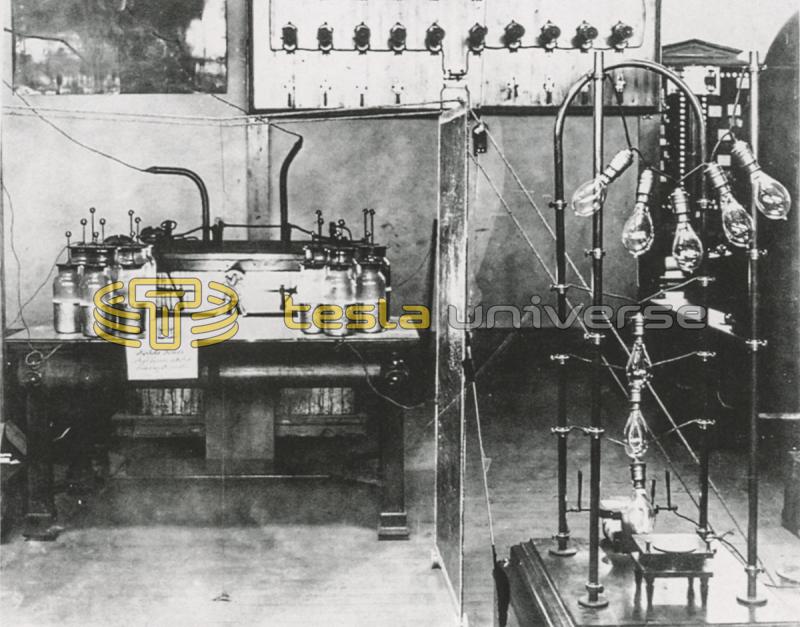
In this space also was arranged a battery of Leyden jars and his large disruptive discharge coil which was used for exhibiting the light phenomena in the dark room. The coil was operated at only a small fraction of its capacity as the necessary condensers and transformers could not be had and as Mr. Tesla's stay was limited to one week; notwithstanding, the phenomena were of a striking character. In the room were arranged two large plates placed at a distance of about eighteen feet from each other. Between them were placed two long tables with all sorts of phosphorescent bulbs and tubes; many of these were prepared with great care and marked legibly with the names which would shine with phosphorescent glow. Among them we noted some with the names of Helmholtz, Faraday, Maxwell, Henry, Franklin, etc. Mr. Tesla had also not forgotten the greatest living poet of his own country Zmaj Jovan; two or three were prepared with inscriptions, like "Welcome Electricians," and produced a beautiful effect. Each represented some phase of this work and stood for some individual experiment of importance. Outside the room was the small battery seen in Fig. 15, for the exhibition of some of the impedance and other phenomena of interest. Thus, for instance, a thick copper bar bent in arched form was provided with clamps for the attachment of lamps, and a number of lamps were kept at incandescence on the bar; there was also a little motor shown on the table operated by the disruptive discharge.
As will be remembered the Westinghouse Company made a fine exhibit of the various commercial motors of the Tesla system and also the twelve generators in Machinery Hall were of the two-phase type constructed for distributing light and power. Mr. Tesla, as is also known, exhibited some models of his oscillators. It was Mr. Tesla's intention to exhibit his motor and high frequency apparatus only during the Congress week, but it was allowed to remain on exhibition on account of a generally expressed desire. Furthermore as Mr. Tesla had only a week's notice to prepare his lecture all his time was taken up for this purpose, otherwise his motor, and especially his high frequency, exhibit would have been more complete.