
Nikola Tesla Articles
A New Tesla Continuous High Frequency Generator
In the forms of high frequency generators heretofore devised by Mr. Tesla, and in high potential generators generally, a cessation of flow has naturally been caused during the interruption of the circuit necessary to obtain the "break." In order to produce a continuous high frequency discharge Mr. Tesla has recently designed the apparatus illustrated diagrammatically in the accompanying engravings.
Briefly stated, the apparatus consists in the combination of two condensers with a circuit-controller of such character and so operated by a single motive device as to charge and discharge the condensers alternately, whereby one will be discharging while the other is being charged, and conversely.
The spaces between two adjacent commutator bars d d', Fig. 2, are equal in are to the width of one of the bars and are filled in with blocks of metal insulated from the other conducting portions of the device. The two heads c c' are insulated from each other. Upon the periphery of this commutator bear three brushes G G' H, the two former resting upon the continuous metallic portions of the two heads, respectively, the latter being in position to bear upon the projections d d' and blocks e alternately.
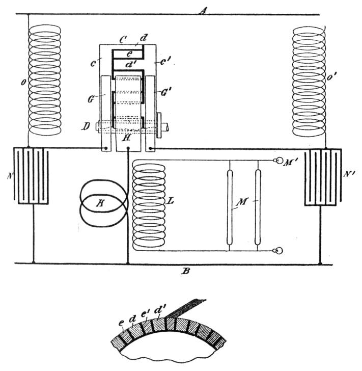
The brush H is connected to the main B through a primary coil K of low self-induction in inductive relation to a secondary L, which constitutes the ultimate source of the current of high frequency which the apparatus is designed to develop. The brushes G G' are connected with the main B through condensers N N', respectively, and to the main A through self-induction or choking coils O O', these latter being used in order that the inductive discharge of the accumulated energy therein may be taken advantage of in charging the condensers.
The operation of the apparatus is as follows: By the rotation of the commutator C the brush H is caused to pass over the projections d, closing the circuits through the primary K and the two cylinders alternately. These two circuits are so adjusted as to have the same capacity, self-induction, and resistance. When this brush is in electrical connection with any projection d' from the part c', the circuit is closed between mains A and B through coil O', brush G', brush H, and coil K. Energy is therefore accumulated in the coil O'. At the same time the condenser N' is short-circuited through the brush G', brush H, and coil K, and discharges through this circuit the energy stored in it, the discharge being in the form of a series of impulses which induce in the secondary L corresponding impulses of high potential. When brush H breaks the circuit through coil O', the high-potential discharge or "kick" from the latter rushes into and recharges the condenser N', but as soon as the brush H has passed over the intervening block e and reached the next segment d it closes the circuit through coil O and short-circuits the condenser N, so that high-frequency currents from either one or the other of the two condensers are flowing through the primary K practically without interruption. Thus without increasing the size or power of the motive device or complicating in any material degree the commutator these devices are made to perform double duty and the output of the apparatus as a whole greatly increased.
It is also evident that all phase differences in the charging and discharging of the condensers may in like manner be obtained, and the same motor and circuit-controller might be made to charge more than two condensers in succession and to discharge them in the same order.
