
Nikola Tesla Articles
Nikola Tesla's Flying Stove
To a Westinghouse manager, Tesla wrote ‘You should not be at all surprised, if some day you see me fly from New York to Colorado Springs in a contrivance which will resemble a gas stove and weigh as much… and could, if necessary enter and depart through a window.'
Margaret Cheney, Tesla: Man Out of Time (2001) pg. 248
An incredible Claim…
My life is a reflection of my lifelong interest in a variety of technical topics. I am a programmer with a degree in Math and Physical Science (+2 years work on a 4 year Master of Theology degree, "to decide for myself"). Engineering captured my interest during my sophomore year in college, and, upon graduation, I started teaching Math, Physics and Chemistry. Naturally, like many Tesla researchers, I built a Tesla coil back when I was in high school, for a Physics class project, Later in life, I found my interest in Tesla renewed when I bought and started reading a book, Tesla, Man of Mystery many years later.
We know that Tesla invented many things which no one else has been able to duplicate since (and, there is a wealth of information locked up where few can get to it - in Belgrade, in the FBI, in the US military -- it is hard to know. They have all been very secretive about it.) Tesla, Man of Mystery is a book that has, along with general information on Tesla and a few fables, one diagram of a device with enough information about it (amid the theories, posturizing, and misinformation) for us to duplicate it. The book called it the "Tesla Space Drive" and it appears to be the heart of what Tesla had said would look like flying on "a gas stove"!

Force Field Generator (Tesla Space Drive)
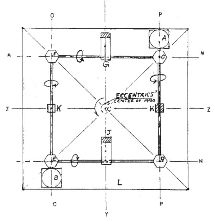
From Page 31 of Tesla, Man of MysteryKey:
• A and B are motors (should be identical)
• C, D, E and F are right-angle drives 1:1 ratio G, H, J, and K are eccentrics
• L is the base plate to which the motors, gear boxes, air pillow blocks (not shown) are fastened M, N, 0, and P are the axes of rotation of eccentrics G, If, J, Lord K
• Y and ‘L are the planes of rotation of the eccentrics Xis the line of intersection of planes Y and Z
Inventions of the past which could have broken oil's strangle-hold on the world economy have always interested me. The Tesla Space Drive appeared to be a motor with tremendous power (maybe over 1,000 times more powerful than magnetic fields) and yet, cheap enough to build in a person's garage, the motor consisted of a few gears and a few symmetrical weights.
It was among several inventions mentioned in the book. However, this one in particular I could visualize from the one drawing provided. The Tesla Space Drive seemed simple enough that it could easily be built in order to either prove or disprove the book's claims.
Design Analysis
My first observation was that the "machine" appeared to be a set of four spinning weights arranged on a simple frame, with no apparent purpose, "peculiarly assembled" as Tesla said about his power generator. Interesting! - It is so simple (easy and cheap!) to build, and yet, it does something Phenomenal!
The object is not spinning nor do any one of the spinning weights match the orbit of the machine and yet, the mass of the object is in orbit - if the object is centered around the four spinning weights like electrons in orbit in a stationary coil - an area in which Tesla is already famous. Instead of acceleration by the left hand rule, (electro-magnetism) now it is by the right hand rule (complete molecules instead of just electrons) according to the author. Even that seems reasonable. (So, for the moment, let's work from that assumption) No one seriously interested in a new, cheap, source of propulsion need question or dispute anything, just build it and find out for ourselves. However, already, we have encountered the first problem. The 4th line of the key to the drawing says: "L is the base plate to which the motors, gear boxes, and pillow blocks (not shown) are fastened."
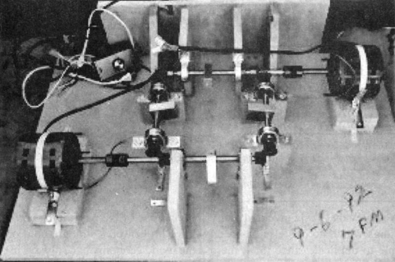
Photo 1: First Construction... the motor was barely strong enough to spin these, smaller weights at maybe 60 to 100 rpm and, they would not spin the slightly longer, heavier, weights at all. I also needed stronger motors.
I traded them in for 1 hp 12 amp motors but was reminded by a friend that household wiring could not handle 2 12 amp motors, so, I traded them for smaller, lighter, 1/5th hp 10,000 rpm ele. motors on 1992-09-21.

No, not true. In just thinking about building my first machine, it became obvious that nothing can be mounted on the base. The weight will spin half-way around and stop when it hits the base on the other side! Everything must be mounted above the base plate, not on it and, after building my first construction (Photo 1) it became clear to me that building it above the frame was not good enough either.
On the next page, he says:
... there is a common point about which the center of mass of the eccentrics and the center of mass of the device as a whole gyrate. (pg. 32)
The meaning of this statement is that everything below the spinning weights must have its counterpart above the spinning weights as well - to be "centered".
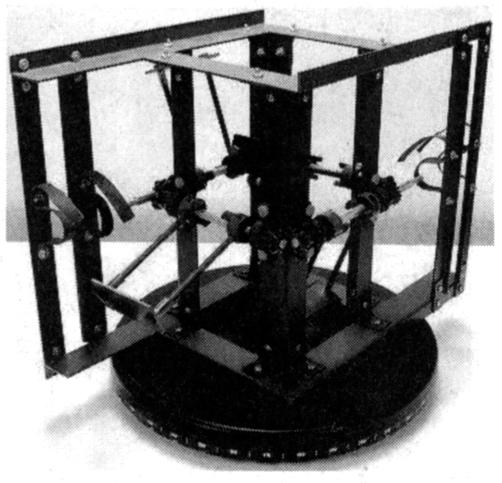
I should have realized that we need two identical plates, one for the top and one for the bottom. We also need four vertical struts placed in a square array symmetrically between the top and bottom plates. The four shafts are mounted around the center points of the four vertical struts with mitre gears (right angle gears) at the corners, keeping them "in sync". A matched pair of motors (A and B in the diagram above), each extending out from the two opposite sides, must be symmetrically mounted so that the center of mass remains at the center of the device as a whole. (See Photo 2 below)

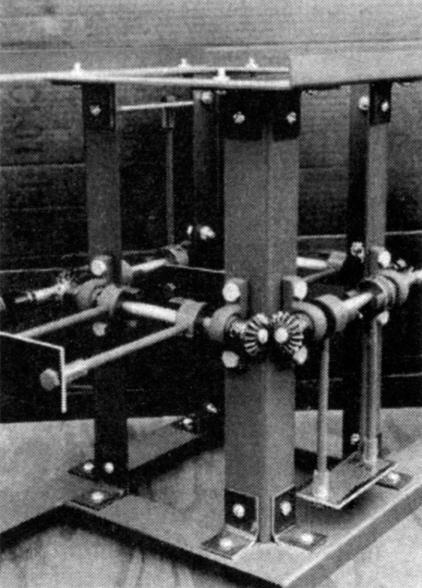
Photo 2: 2nd Tesla Flying Machine design
Since nothing is said about weight being an issue, my second (all steel) frame was built to be rigid, not lightweight. I estimated the weight to be about 30 lbs plus about 15 lbs in motors, pillow blocks, steel drive shafts. etc.
After spending over $200 to have this iron frame built ($275 paid on 2-18-1993), I tested it. The new motors would spin the weights, washers on short bolts, but, one or two often came loose at start-up. The ele. motors accelerated them too fast. It was difficult to screw them on tight enough. When they were on tight enough and they did spin, the frame did not bounce around or even vibrate significantly but, it did not lift off either. I realized I would have to figure out the necessary speed to enable the device to move.
I drafted a clearer version on the opposite page. I admit, I left out the motors in this diagram (see first diagram, pg. 31, above), since there is no design specification for them. They can be anything you can get hold of. The only requirement is that they be able to get your weights up to your needed speed.
However, the book, does not mention a speed requirement (for the eccentrics) except to say:
[It will] wobble noticeably at low thrust (rpm) levels. This effect fades out, however, as the thrust (rpm) is increased.
Force Field Generator...
Greg Smith's Best Version
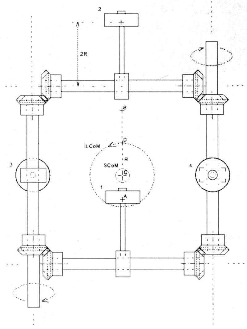
SCoM = orbit of System's Center of Mass
ILCoM = orbit of Inertial Load's Center of MassNote #1:
In the drawing (Fig.1) the centers of mass (aka gravity) of loads 1 and 2 are each marked with a ‘+'. As shown, the center of mass for load #1 is at ‘A'. The center of mass for #1 and #2 combined is exactly halfway between their two individual centers, at point ‘B'. The center of mass for #3 and #4 combined is halfway between their two individual centers, at point ‘C' (since load 3 is the same distance down (2R) that load 4 is up, ‘C' is at the center of the frame with respect to all 3 coordinates). The center of mass for all four combined, is halfway between ‘B' and ‘C', at point ‘D' and that Radius, from C to D, is labeled R. Since ‘B' is the midpoint between #1 and #2 and is also always at the ‘2R' distance (the radius of each individual mass) from the center ‘C', ‘R' (the radius of ILCoM) is always 1/2 the radius of the individual weights (because only two out of four are shifting in each direction - front to back or side to side).Note #2:
Example: If the total system weight, the four inertial loads included, is 10 times the sum of the weight of the four inertial loads, by themselves, then the ratio of the SCoM to ILCoM is 1:10 and the ratio of the SCoM to the radius of any one of the loads, weights, is 1:20. If the arm, rod, holding any one of the weights is about 3cm long, then the orbit of the center of mass is 1/10 of 1/2 of that or, about 0.15cm.General Notes:
The four weights are not the only loads on the system. If the four weights revolve fast enough, the air resistance becomes an additional load. If the rpm of the weights is doubled, the radial load on the shafts is quadrupled (mass x radius x rpm x rpm x K = force).

Key to Smith Version Drawing:
1. Four identical Inertial Loads (weights, masses) (labeled 1 through 4) are mounted on four identical arms (of length 2R) which, in turn, are mounted on four identical shafts arranged on a square. The shafts are geared so that they stay synchronized:
1:1 ratio right angle drives (aka "mitre" gears).
This unique arrangement for the four inertial loads is such that, as they revolve about their axes, their collective center of mass (center of gravity) takes on a circular orbit where the center of the orbit is also the center of mass of the rest of the device. This aggregate circular orbit is the first necessary condition and is labeled ILCoM (the orbit of the four Inertial Loads Center of Mass). (See note #1 for detailed exposition.) It is the induced orbit in the center of gravity of the stationary object, the frame, which forces a reaction from the object, a linear acceleration according to the right-hand-rule.
2. Whatever collection of materials is used to mount and rotate the shafts, for an initial point of reference, the center of mass of the frame (the entire device minus the four weights) is at the center of the square array of shafts (labeled C in the drawing).
3. If ILCoM is the orbit of the four Inertial Loads' (weights) Center of Mass and if the weight of the entire system (device), the 4 loads included, is 10 times the weight of the 4 loads by themselves, then the radius of orbit of the System's Center of Mass (SCoM) will be 1/20th of ILCoM. (See note #2)
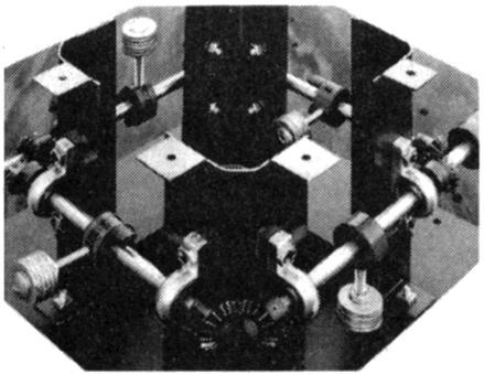
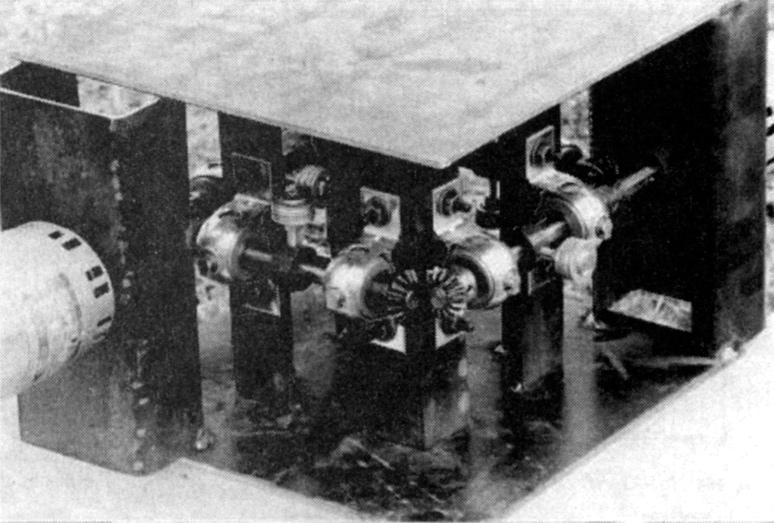
Third model, with 10,000 rpm electric motors: The shafts and pillow blocks are also, now, aluminum alloy. This model was fine but the frame was just a little flimsy (the top was removed for the purpose of the bottom photo) Note: I used the red/orange (Lovejoy) jaw couplings because they were a cheap easy way to attach weights on a shaft. I just replaced the set-screws with bolts.

Operating Principles of the Force Field Generator / Motor
This device converts inertial energy into centrifugal acceleration which, according to the right-hand rule, generates linear acceleration. The principal is the same for the way that the centrifugal acceleration of electrons, in a coil, exert linear acceleration on a metal rod placed in the center of the coil. Here, the acceleration is exerted on the frame.
An electric motor is the result of electrons in orbit; this motor is the result of entire atoms, the entire device, in orbit. The rotation (rpm) necessary to generate acceleration depends upon:
- the mass of the entire device
- the mass of the four rotating inertial loads, (four masses),
- the radius of those four loads (four eccentrics, four masses)
- and, the force of gravity
For example, if the mass of the four inertial loads totals 1/10th the total mass of the entire device, then the radius of rotation of the center of mass of the system (the entire device) is 1/20th that of the radius of any one of the rotating loads. (Not 1/10th. This is just geometry but, I overlooked it for a time) (only two of four weights go left to right and the other two of four go front to back). It is the rotation of the entire system (device) that must get up enough centrifugal acceleration to defeat gravity.
I had learned how to calculate the necessary speed required, not mentioned in the book. Still, I made an error in my calculations and thought I needed more speed than was the case - and my motors were inadequate - I thought.
I did build it and, though it did not get "up to speed", we were close, closer than I realized. A friend, with some of the equipment that I needed to use, was even more impressed than I was that "Something is going on here". As we experimented with lighter weights and higher speeds, we expected that the vibrations would diminish, but, they intensified instead.
"Not enough Information"?
I had Tesla's biography Man Out of Time, by Margaret Cheney, a thick, well received, book with lots of reliable information on the man. There I found how Tesla had contracted with both Allis Chalmers and with Westinghouse's railway and lighting division to build a 36,000 rpm turbine to "fly from New York to Colorado Springs in a contrivance which will resemble a gas stove" (letter dated July 7, 1912).
If the turbine was to be a, relatively, lightweight power source to drive it, then it was the turbine that stopped Tesla. The metals of his day stretched under the centrifugal forces and he got no further, publicly. By 1979, the Tesla turbine was once again under development as a power source. According to SunWind Ltd (3-12-79):
The turbine is inexpensive and easily machined.
In addition to weak metal alloys, Tesla had to contend with "negative reports" from engineers who did not understand his designs "claiming they would not build it as he wished... They said he refused to supply enough information." Maybe, again, they just could not understand something from Tesla "which had no theoretical precedent". (They probably thought they had to build something to some high precision which Tesla had not specified - because Tesla knew it was not necessary.)

Second Tesla Space Drive design
Since nothing is said about weight being an issue, my second (all steel) frame was built to be rigid, not lightweight. It was right after this that I figured out the speed requirement and the variables that affect it.
Constructing this device gave me some insights as to Tesla's frustrations. A crude drawing and brief description was all I had to construct this device. Talking to an engineer took an undue effort on my part to convince him that the center of gravity of the device, does travel in a circle. How could I explain that a force is generated "according to the right hand rule" (as opposed to the left hand rule for electricity)? How did Tesla know that? And, even if sliding the motor a little off-center, in different directions, could control speed and direction, how did Tesla know how much movement is needed? How did he "SEE" that in his mind, the way he seemed to see everything that he intended to build?
Final design: January 1994 using .090 inch aircraft aluminum ($9) and two 22,000 rpm air motors ($50) the frame is rigid and the motors are very light weight. I made the frame taller to accommodate longer arms and, slower speed requirements but, that was not necessary. However, there is an increased strength and reduced stress benefit to the double arms.

Basic Operation Concepts
An electrical coil sends electrons flying in a circle, in orbit about a center-point that is not the nucleus of the atom. The coil is sitting there, going nowhere, but its electrons are flying around in orbit and that paradox sets up a magnetic force-field. The coil is just sitting there. Nothing is seen to be moving. But a voltage is applied and suddenly a magnetic force field appears and things do visibly start moving!
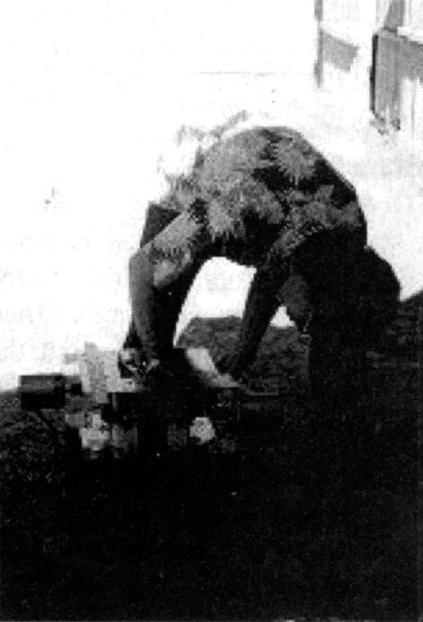
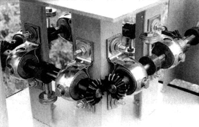
Experimentation is a major part of research. Here we test a 1993 model. What we learned from it from was incorporated into other designs.

Here we have a frame with some weights flying around in circles, going nowhere, just spinning, but it is "peculiarly assembled" and the net result is that the center of gravity of the entire device, still just sitting there, is in orbit - now we have the same paradox but the center of mass of the entire object is in orbit, not just the electrons. Now, we have the potential for an atomic force field - the entire atoms are generating an orbital force field instead of just the electrons. Atoms being about 2,000 times more massive than their combined electrons, the force being generated here could be a few thousand times stronger. Because the protons are the charged particles doing the work, instead of the electrons, the force operates by the right-hand rule.
However, even the 1/2 hp air motors were not quite powerful enough to handle the weight/inertia of the "eccentrics". We could not seem to deliver the full air pressure in the tank to the motors and it did not occur to me to reduce the weight of the eccentrics even more, where the motors might have the power necessary. The two air motors were great. They totalled only 24 oz. The massive air compressor was not part of the "system". Knowing that even if it takes off so fast that it breaks loose from the air hoses is no problem. Just proving that it works is enough to "turn heads" and start things rolling - more likely, it will just start to slowly lift off and we will be so startled that we will shut it down.
I have been told by an engineer that slight imperfections in the balance and geometry of the system are nothing compared to the imbalances caused by the rotating weights. So that is a minor issue. Get "close enough" and we should be fine. From experience, I can tell you that the electric motors I used, started up so fast that one or more weights often came loose. The air motors gave more control.
In March 1994, we tried it with three, two, and then only one crossbar. With only one crossbar, I think we got 200 to 300 rpm out of the motors. A friend said "Something is happening here." It started shaking more, not less, when we reduced the weights (from two to one on each side) and got it spinning faster. Instead of shaking less, it did the opposite. Something was happening.
More Research…
October 2007:
After a long hiatus, I resumed research on Tesla's Space Drive. A few weeks ago, I tried it without any crossbars but, the weight and inertia were still too much for the motors.
November 2007:
I bought 2.5" bolts and 1.5" bolts so I have two more options. If the 2.5" does not reduce the weight and inertia enough to enable the motors to get up some significant speed, I can try the 1.5" bolts.
Cutting the length and weight in about half (from 4.75" to 2.5" bolts) reduces our net radius from about .1" to about .025" and our needed speed from about 600+ rpm to about 1200 rpm. Although it was an improvement, it just was not enough improvement and we switched to the 1.5 inchers.
We started it up and the speed finally seemed greatly improved. A mechanic said it looked like it was going about 5 or 6,000 rpm. Great! Finally! Still, nothing more happened and we turned it off.
December 2007:
Afterwards, I realized several potential problems. First, the force may have been exerted downward instead of up (we need to try turning it upside down) and, second, the two air hoses were adding weight to the system, holding it down. We needed to prop the hoses up so that they do not add weight to the system.
January 2008:
We tried it again, right side up and upside down. We held up the two air hoses. We got several thousand rpm, more than enough, and yet, no movement, no "lift". Well, it didn't work.
Unless we can think of something we overlooked, at this point, we are at a dead end... but who knows what the future may hold!
While I may not have realized Tesla's Space Drive yet, perhaps this article will inspire others to take up the cause. In the interim, I have other projects to work on, and perhaps one of them may hold the key to limitless power!
