
Nikola Tesla Articles
On Polyphasal Generators
American Institute of Electrical Engineers.
New York, December 160th, 1891.
The sixty-second meeting of the American Institute of Electrical Engineers was held this date at No. 12 West 31st street. The meeting was called to order by Secretary R. W. Pope.
The Secretary: - Gentlemen, it gives me pleasure to announce that we have with us this evening our esteemed Past President, Professor Elihu Thomson, and in view of the fact that he is not very frequently present, we have induced him to preside over the meeting to-night, but it is understood that he will not refrain from taking part in the discussion should occasion warrant.
The Chairman [Prof. Thomson]: - On being asked to preside this evening, I protested that I did not believe I was a Vice-President of the Institute, but the plan seems to be that I shall make up to some extent for my remissness in the past. When I was President of the Institute I did not get down to many meetings, except the annual meetings, and I will take pleasure in doing what I can now to make up for that remissness, if my services are of any use to the Institute.
The proceedings of the evening will commence with the paper "On Polyphasal Generators," by Dr. M. I. Pupin, of Columbia College.
A Paper read at the sixty-second meeting of the American Institute of Electrical Engineers, New York, December 16th, 1891. Past-President Thomson in the Chair.
On Polyphasal Generators.
By M. I. Pupin, PH. D., Columbia College.
Few will deny the importance of the polyphasal current systems; none the fascination of their study. This belief induced me to present the following brief essay before the Institute.
The experimental researches in this new and promising field of electrotechnics are not yet numerous, but still the results already obtained are of so decisive a character as to leave no doubt whatever as to the extremely high practical importance which is attached to electrical generators, motors and transformers constructed according to requirements imposed upon us by this new method of combining a set of variable electromotive forces. For who among us does not thoroughly appreciate the beautiful inventions of Nikola Tesla and the completeness of the success which Dobrowolsky and Brown obtained by the practical applications of these inventions?
The exact quantitative relations involved in the polyphasal system of currents are not, I venture to say, quite as well known as its practical results. To give an impulse to further inquiry in that direction is one of the principal aims of this modest investigation. For the present I propose to confine myself to the polyphasal generators in general, and particularly to polyphasal generators whose system of electromotive forces is capable of producing a rotary magnetic field of constant strength. The last point seems to me to be one of the vital points in this new method of electrical distribution. It is in this particular point that Mr. Dobrowolsky claims his system to be superior to that of Nikola Tesla.
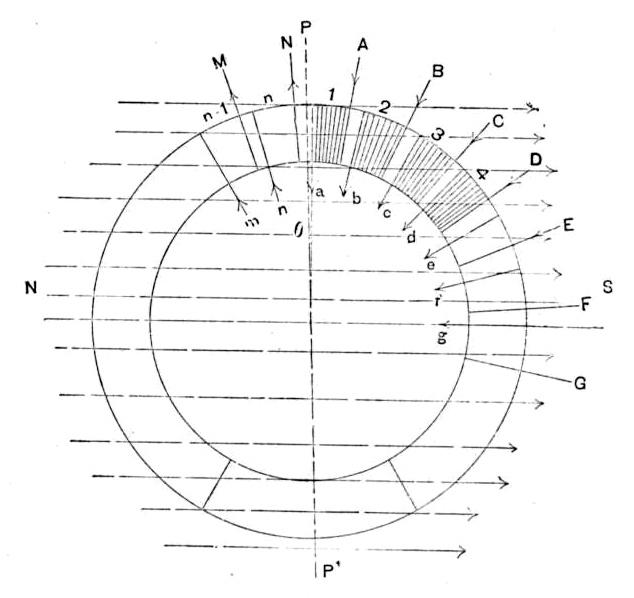
Let us consider the theoretically simplest form of a polyphasal generator, as shown in Fig. 1. A non-magnetizable ring with n open equal coils at equal distances from each other rotates uniformly through a perfectly homogeneous magnetic field. Let PP' be the neutral plane of the field. At the instant when coil 1 is at the angular distance θ from the neutral plane PP' the E. M. F. generated in the various coils will be
$$ e_1 = K sin (θ+α)$$
$$e_2 =K sin (θ+α+ \frac{2!$ \pi !$}{n})$$
$$ ........ ........ ........ ........ $$
$$ ........ ........ ........ ........ $$
$$ e_n = K sin \lbrace θ+α+(n-1) \frac{2!$ \pi !$}{n} \rbrace $$
Where K is a constant depending, as is well known, on the field intensity, the speed of rotation, the number of turns in the coil and the area of the plane of a turn; a is the angular width of one-half of the coil.
Since
$$sin (θ+α) + sin \lbrace θ+α+\frac{2!$ \pi !$}{n} \rbrace + ...... + sin \lbrace θ+α+(n-1) \frac{2!$ \pi !$}{n} \rbrace = 0$$
it follows that
$$e_1+e_2+e_3+ ...... + e_n = 0 ...... (1).$$
That is to say, the sum of electromotive forces generated in the various coils which are on one side of the neutral plane is numerically equal and of opposite sign to that of the coils on the other side of this plane. This result is well known and self-evident. It is, however, far from self-evident that relation (1), which I shall call the relation of continuity for the electromotive forces, will be satisfied by every magnetic field.
Close each coil separately by conductors of equal resistance and self-induction. Let c1, c2 ...... cn denote the currents in the n separate circuits. It is evident that
$$ c_1 = \frac{K}{I} sin (θ+α-φ)$$
$$ c_2 = \frac{K}{I} sin (θ+α+ \frac{2!$ \pi !$}{n} -φ)$$
$$ c_3 = \frac{K}{I} sin (θ+α+ 2\frac{2!$ \pi !$}{n} -φ)$$
$$ c_n = \frac{K}{I} sin \lbrace θ+α + (n-1) \frac{2!$ \pi !$}{n} - φ \rbrace$$
Where I is the impedance in each circuit and φ the angle of retardation. Hence, we have
$$ c_1 + c_2 + c_3 + .... ... +c_n = 0 ...... (2).$$
That is to say, the relation of continuity is satisfied for the currents also.
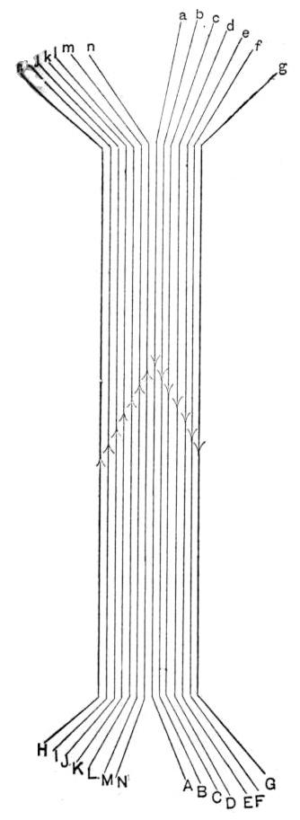
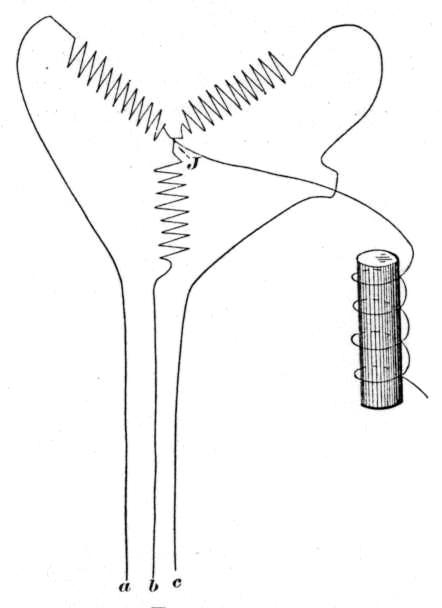
Let the wires aA, bB, ...... nN (Fig. 2) represent a part of each of the n conductors of this system. Then, according to relation (2), the sum of the currents in these n linear conductors being always zero, if we joined them all into one conductor there would be no current in this wire, but the currents in the n circuits would circulate exactly the same as before. In fact, the common juncture is useless and can and should be cut out.
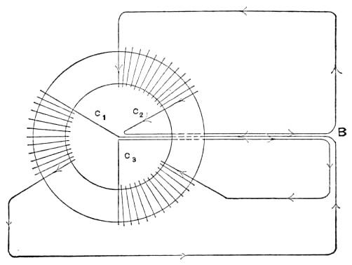
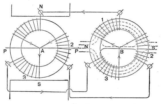
The diagram, Fig. 3, represents this method of connecting for a three-phase system. Consider, now, n equal coils distributed at angular distances of \(\ \frac {2!$ \pi !$}{n} \) over a laminated iron ring B, each coil being a part of the n conductors coming from the generator. Diagram Fig. 4 illustrates this for a three-phase system. Let the n currents be denoted now by c1', c2', ...... cn'. We shall have now,
$$ c_1 ' = \frac{K}{I'} sin (θ+α-φ')$$
$$ c_2 ' = \frac{K}{I'} sin (θ+α + \frac{2!$ \pi !$}{n} - φ')$$
$$ c_n ' = \frac{K}{I'} sin \lbrace Θ + α + (n-1) \frac{2!$ \pi !$}{n} φ' \rbrace $$
and, therefore,
$$ c_1' + c_2' + ...... +c_n' = 0 (3) $$
The introduction of the iron ring with the n coils into the n phasal system has changed the impedance I, and the angle of retardation φ; but this change is evidently the same for all coils. The correctness of this statement might, perhaps, be questioned, if we supposed that the system of the n variable currents was at any moment strong enough to saturate the iron ring, I therefore suppose that the intensity of magnetization in the ring is never over 10,000 C. G. S. lines of force. We shall presently see that in the case of a properly built generator the saturation of the iron ring will not vitiate the correctness of the above statement in the slightest.
Let s be the number of turns in each of the n coils. Relation (3) gives
$$ 4 !$ \pi !$ s c_1' + 4 !$ \pi !$ s c_2' + ... ..... + 4 !$ \pi !$ s c_n' = 0 (4)$$
That is to say the magneto-motive forces in the n coils of the ring b satisfy the relation of continuity. Relation (4) translated into physical language means that the magnetization in the iron ring is due to two equal magneto-motive forces working in multiple arc. The magnetic field produced is perfectly symmetrical with respect to the ring as indicated by the dotted lines in Fig. 4.1
Consider now n iron ring cores of exactly the same dimensions and made of the same material. Let ρ be the reluctance of each ring. Let each of the n coils be interlinked with one of the iron rings, we shall have n homogeneous magnetic circuits; and as long as the magnetization of these rings is considerably below the saturation point, we shall have
$$ \frac {4!$ \pi !$sC'}{ρ} + \frac {4!$ \pi !$sC'_2}{ρ} + ... \frac {4!$ \pi !$sC_n'}{ρ} = 0 $$
That is to say the magnetic induction in the n magnetic circuits obeys the same law as the n electric currents; we can therefore employ the method of polyphasal connection for the magnetic circuits also and we obtain what the Germans call a Verkettung der Magnetischen Kreisläufe which may be translated into English by a more accurate expression: Polyphasal coupling of magnetic circuits. A transformer constructed on this principle may be called a coupling transformer, to distinguish it from the Tesla polyphasal transformer.
A simple consideration will show that the field rotates around the axis of the ring B synchronously with the rotation in the generator which produces the impressed E. M. forces. Consider the armature of the generator. Since the ampere turns on one side of the neutral plane is always equal and opposite in sign to the ampere turns on the other side of this plane it is evident that the magnetic field due to the ampere turns in the armature is fixed in space and perfectly symmetrical with respect to the plane of symmetry PP1. We can therefore say that this field, though fixed in space, rotates with respect to the armature with the same angular velocity with which the armature rotates in space. The distribution of the ampere turns over the stationary ring B being at any moment the same as that over the armature ring, it follows that the magnetic field of B also rotates with respect to B synchronously with the rotation in the armature. An inspection of the diagram in Fig. 4 will show that when the rotation in the generator is reversed the rotation of the field B will also be reversed.
The strength of the rotating magnetic field will vary because the strength of the two equal magneto-motive forces which are working in multiple arc will vary. The following simple consideration will show us the law of this variation. Two cases must be considered separately. First, when n is an odd number; secondly, when n is an even number.
Case 1.
A simple definition will save me the tedious repetitions of long sentences. I define the sum of all the electromotive forces generated in all the turns which are at any moment on the same side of the neutral plane of the generator as the resultant impressed E. M. F. at that moment. The magneto-motive force of the rotating field will evidently vary according to the same law the resultant impressed E. M. F. To find the law of variation of the resultant impressed E. M. F. consider the armature of the generator when the angle Θ of coil 1 is zero. To make the reasoning shorter, I make now the angular width of each coil equal to \(\ \frac {2!$ \pi !$}{n},\) so that the n coils completely cover the ring, which makes \(\ α = \frac {!$ \pi !$}{n}.\) If this angular width is smaller, then a simple consideration will show that the law of variation which I am about to deduce will be exactly the same. In the position just mentioned, the coils \(\ 1, 2, 3, ... \frac{n \quad 1}{2}\) will all be on the same side of the neutral plane, whereas coil \(\ \frac {n+1}{2} \) will be just half on one side and half on the other side of this plane. There is no electromotive force generated in this coil. As the above mentioned angle Θ begins to increase from zero, coil \(\ \frac {n+1}{2} \) begins to contribute to the resultant impressed E. M. F., but this contribution is just counterbalanced by the loss due to the entrance of coil n into the opposite region of the neutral plane. The variation in the resultant impressed E. M. F. is therefore due solely to the change of position of the turns in the coils \(\ 1, 2, 3, ... \frac {n-1}{2}, \) or one side and the corresponding turns on the other side of the neutral plane. This will be the case until coil \(\ \frac {n+1}{2} \) has completely passed to one side of the neutral plane and coil n is just bisected by it. During this interval Θ has increased from zero to \(\ ½ \frac {2 !$ \pi !$}{n} = \frac {!$ \pi !$}{n}. \)
The value of the resultant impressed E. M. F. at any moment during this interval is easily found. Denote it by E, then
$$ E = e_1 + e_2 + ...... \frac {e_n - 1}{2} $$
$$ \quad = K \lbrace sin (θ + \frac{!$ \pi !$}{n}) + sin (θ + \frac {!$ \pi !$}{n} + \frac {2!$ \pi !$}{n}) + ...... + sin \lbrace θ + \frac {!$ \pi !$}{n} + (\frac {n-1}{2} - 1) \frac {2!$ \pi !$}{n} \rbrace $$
$$ \quad = K \lbrace sin (θ + \frac {!$ \pi !$}{n}) + sin (θ + \frac {!$ \pi !$}{n} + \frac {2!$ \pi !$}{n}) + ...... + sin \lbrace θ + \frac {!$ \pi !$}{n} + ( \frac {n - 3}{n} ) \frac {2!$ \pi !$}{n} \rbrace $$
\[
=\left\{
\begin{aligned}
& \frac{K_1 \sin\left( \theta + \frac{\pi}{n} + \frac{n-3}{4} \frac{2\pi}{n} \right)}{\sin \frac{\pi}{n}}
\end{aligned}
\right\}
= K_2 \sin\left( \frac{\pi}{2} + \theta - \frac{\pi}{2n} \right)
= K_2 \cos\left( \theta - \frac{\pi}{2n} \right)
\]
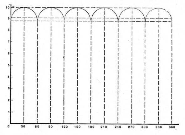
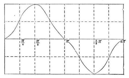
It is evident that the resultant impressed E. M. F. E varies during the interval from \(\ \Theta= 0 \) to \(\ \Theta = \frac{!$ \pi !$}{n} \) just like \(\ cos (\Theta - \frac{!$ \pi !$}{2n}); \) that is to say, it varies just like a simple harmonic. When \(\ \Theta = \frac{!$ \pi !$}{2n}, \) E reaches a maximum which is equal to K2, it has a minimum both when \(\ \Theta = 0 \) and when \(\ \Theta = \frac{!$ \pi !$}{n} \), each of these minima equals \(\ K_2 cos \frac{!$ \pi !$}{n}.\) The ratio of the minimum to the maximum value equals \(\ cos \frac{!$ \pi !$}{2n}.\) For a three-phase system this ratio is .866, and it diminishes very rapidly as n increases. It is evident that after Θ has reached the value \(\ \frac {!$ \pi !$}{n} \) the armature is, as far as concerns the resultant impressed E. M. F., in exactly the same position as at the start when Θ = 0. We conclude, therefore, that E has 2n equal maxima and 2n equal minima during each revolution of the armature. In diagram Fig. 5 these fluctuations of E for a three-phase system are represented graphically.
Case 2.
Similar relations hold good when n is even. The maxima take place when \(\ \Theta = 0, \frac{2!$ \pi !$}{n}, \frac{4!$ \pi !$}{n}, ...... \) The minima when \(\ \Theta = \frac{!$ \pi !$}{n}, \frac{3!$ \pi !$}{n}, \frac{5!$ \pi !$}{n}, ...... \) and the ratio of any minimum to any maximum is \(\ cos \frac{!$ \pi !$}{n} \). Since the magneto-motive force varies according to the same law as the resultant impressed E. M. F., it follows that the strength of the rotary magnetic field fluctuates periodically, having 2n equal maxima and 2n equal minima during each revolution, and the ratio of any minimum to any maximum equals \(\ cos \frac{!$ \pi !$}{2n} \). That is, when n is odd; but when n is even then there are only n maxima and n minima, and the ratio of any minimum equals \(\ cos \frac{!$ \pi !$}{n} \).
A polyphasal generator of this kind would produce a rotary magnetic field of constant strength only when n = ∞. For a three phase system the maximum variation would be nearly 14 per cent. of the maximum value. This agrees perfectly with Mr. Dobrowolsky' s calculations, but I fail to see how these calculations could justify any one to assume that they hold good for all types of polyphasal generators2. The generator which we have considered could be actually constructed but its output would be so small in proportion to its size that we may dismiss it at once as an impracticable machine. We can make it practicable by substituting for the non-magnetizable ring which carries the armature coils a laminated iron ring, and for the uniform magnetic field, the magnetic field of a well made field magnet with its pole pieces placed with respect to the armature coils in any one of the various ways sanctioned by practical experience. But in a generator of this kind the resultant impressed E. M. F. will no longer vary according to the law which I have pointed out a little while ago. To be sure, we shall still have the same number of maxima and minima, as may be inferred readily from our knowledge of the shape of the E. M. F.curve of a continuous current dynamo. We all know that this curve is not in general a straight line, but a wave line having as many maxima and as many minima as there are sections on the commutator. But the ratio of the maxima to the minima is no longer an a priori calculable quantity. If we knew the mathematical relation between the intensity of the field at any point of the armature surface and the co-ordinates of this point with respect to the neutral plane then we could calculate that ratio, but the amount of experimental and practical work involved in this problem would be very great. A much easier and practically much more important problem is to determine the conditions which must be fulfilled in the construction of a polyphasal generator, in order that it may be capable of producing a rotary magnetic field of practically constant intensity in the simplest possible way, that is without the application of brushes and commutators, and also without employing too many phases. Mr. v. Dolivo-Dobrowolsky seems to think that a three phasal generator is incapable of doing that, for he distinctly says that such a generator necessarily produces a rotary magnetic field whose strength varies 14 per cent. He also states that (evidently to obviate these fluctuations) the Allgemeine Electricitæts Gesellschaft employ a method of transmitting currents of smaller differences of phase than one-third of the period through three wires. In this point they claim to be ahead of Tesla, Bradley, Haselwander and Wenstrom. In fact if one is not exceedingly careful in the perusal of Dobrowolsky's discussions of this subject he will be led to believe that the rotary field in some of Tesla's motors varied as much as 40 per cent. and certainly not less than 14 per cent. I do not think that Mr. Dobrowolsky wishes to be understood as holding that opinion; for neither he nor anybody else excepting Tesla himself can know what these variations were. The number of phases employed tells us nothing definite about the range of these variations.
A polyphasal dynamo which is capable of producing a rotary magnetic field of constant intensity must be constructed in such a way that its resultant magneto-motive-force must remain constant as long as speed and the magnetic field of the field magnets remain constant. As long as the variable electromotive force developed in each coil follows the law of a simple harmonic that result can never be accomplished by a finite number of phases, but it may, perhaps, be accomplished by producing in each coil a variable electromotive force which varies according to some definite complex harmonic law. In a well made commercial machine the electromotive forces developed in the various turns of the armature always vary according to some such a law. The form of this complex harmonic law depends on the form of the magnetic field of the field magnets and also on the distribution of the coils over the armature. The problem that remains to be investigated consists therefore of three parts: 1st. What must be the particular form of the complex harmonic E. M. F. developed in each coil of a polyphasal generator, in order that both the condition of continuity be fulfilled and also that the resultant impressed E. M. F. be continually constant. 2nd. What form of the magnetic field of the field magnets will be capable of producing such an E. M. F. 3d. Can a continually constant resultant E. M. F. produce a rotary field of constant strength.
1st. The first part of this problem is purely mathematical. In a paper read before the New York Mathematical Society I indicated a method of discussing this part in a general way, and worked out completely two particular cases, namely the cases of a three and four phasal system. The paper is given in the appendix.
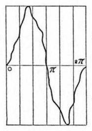
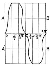
2d. For a three phasal system the form of the complex harmonic E. M. G. given in Fig. 7. will satisfy all the conditions. The form A, B, C, E, F, given in Fig. 8, is only a particular case and ought to be aimed at in the construction of the machine.
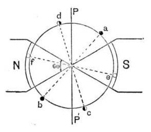
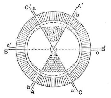
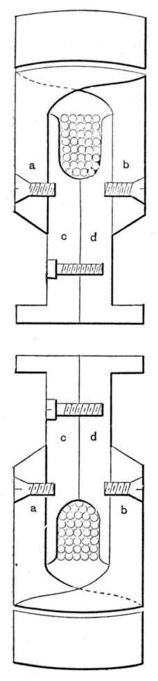
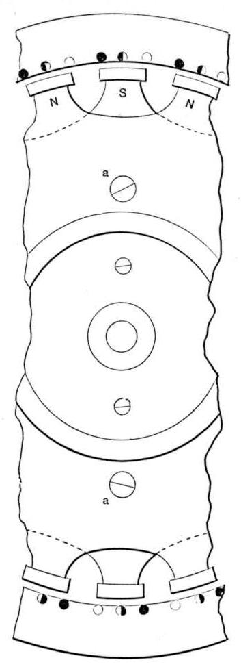
When there are only three turns within a space through which the armature moves with respect to the field during the time that corresponds to a complete period as in the case of the Lauffen generator (see Figs. 11 and 12), then the field of the field-magnets must be constant in intensity during an angle which corresponds to one-sixth of the period. I have indicated that, in the diagram Fig. 9. In the case of bipolar three phasal generators as indicated in the diagram Fig. 10, where we have six coils, the diametrically opposite pairs being connected in series; the pole faces must have an angular width of 120 degrees and the field must be constant in intensity within the region bounded at any moment by the armature and the pole faces. This is a practical problem offering no serious difficulties judging from the experimental results obtained by S. Thompson, Isenbeck, Mordey and others, and also from the experimental results obtained lately by a graduate of our school, Mr. Freedman, John Tyndall Fellow of Columbia College.
The curve of impressed E. M. F., which must be produced in the case of a four phasal generator is given in Fig. 13, and needs no further commentary. Larger number of phases offer no special advantages whereas the disadvantages arising from employing a large number of phases are self-evident.
3d. When a coil, in which a simple harmonic E. M. F. is developed is closed by a resistance, whether self-inductive or non-self-inductive, the current which is set up in the closed circuit will be a simple harmonic, having therefore all the characteristics of the impressed E. M. F. This, however, is not necessarily the case when the impressed E. M. F. is a complex harmonic. A complex harmonic E. M. F. is composed of a large number of simple harmonic E. M. forces of different frequencies, all the higher frequencies being multiples of the fundamental frequency. When, therefore, a coil in which a complex E. M. F. is generated, is closed by a conductor, and the current is started, the current will be also a complex harmonic, each simple harmonic component of the complex harmonic E. M. F. producing its own simple harmonic current which is a component of the resultant complex harmonic current. But since the component simple harmonic E. M. forces have each a different frequency, it follows that they will have a different impedance and the shifting of phase will be also different for each component current, currents of higher frequency having a larger shifting in phase and also the ratio of the amplitude of any one of the component currents to the amplitude of any other component of lower frequency, being smaller than the ratio of the amplitudes of the corresponding component E. M. forces. In this respect the propagation of the complex harmonic current-wave resembles very much the propagation of a complex harmonic sound-wave or a complex harmonic light-wave through an absorptive medium like air. The component simple harmonic waves of light and sound will in general suffer the less through the transmission the longer their wave-length. Just as the sound and light-waves, after such a transmission, lose a great many characteristics of the original vibration which produced them, so an electric wave in its transmission through a conductor possessing ohmic resistance and electro-magnetic, not to speak of the electro-static, inductance will lose a great many characteristics of the impressed E. M. F.
To put this into simple symbolic language of mathematics,
Let L be the coefficient of self-induction of the circuit,
Let R be the total resistance,
\(\
K \sum_{m=1}^{\infty} a_m \sin mpt
\) be the complex harmonic impressed E. M. F., where p = 2!$ \pi !$ × fundamental frequency,
Let x be the value of the current at any moment t. We shall have, then \(\ L \frac{dx}{dt} + R x = K \sum_{m=1}^{\infty} a_m sin \; m p t\).
The solution of this differential equation gives
\[
x = K \sum_{m=1}^{\infty} \frac{a_m}{\sqrt{R^2 + m^2 p^2 L^2}} \sin(mpt - \varphi_m)
\]
where \(\ tan \; α_m = \frac{mpL}{R} \).
The current x is a complex harmonic, its component simple harmonic currents being
\(\ x = x + x_2 + ..... + x_m + ..... \) ad infin.
The current \(\ x_α = \frac{Ka_α . . . }{\sqrt{R^2 + a^2 + p^2 + L^2}} sin (α p t - φ_α) \)
$$ tan \; φ_α = \frac{a p L}{R.}$$
Let E be the impressed E. M. F., then
$$ E = e_1 + e_2 + e_3 + ........ + e_m + ....... ad\; infin.$$
The component simple harmonic E. M. F. \(\ e_α \), is given by
$$ e_α = a_α sin\; a p t.$$
These relations give an exact quantitative expression to the preceding physical description.
These considerations made me hesitate at first in taking as granted that a polyphasal generator producing complex E. M. forces, such as I deduced mathematically in the course of my paper, would be capable of producing a rotary magnetic field of constant intensity. But I was glad to find out that my hesitation was groundless, at any rate in certain particular but important cases.
Consider the three-phasal generator whose diagram is given in Fig. 10. Take, now, another well-laminated armature wound in a similar way as the armature of the generator. Connect the three pairs of coils of the generator to the three sets of coils in armature 2. We shall have three separate circuits, the ohmic resistance and the self and mutual inductance in each circuit being the same. Denote by E1E2E3 the three complex harmonic E. M. forces in the three circuits. Let x, y, z be the currents at any moment. Then we shall have
$$ L \frac{dx}{dt} + M \frac{dy}{dt} + M \frac{dz}{dt} + R x = E_1 $$
$$ L \frac{dy}{dt} + M \frac{dx}{dt} + M \frac{dz}{dt} + R y = E_2 $$
$$ L \frac{dz}{dt} + M \frac{dx}{dt} + M \frac{dy}{dt} + R z = E_3 $$
But since \(\ E_1 + E_2 + E_3 = 0 \) for all values of t it follows that \(\ L \frac{d}{dt} (x+ y + z) + 2 M \frac{d}{dt} (x + y + z) + R (x + y +z) = 0 \) for all values of t. This can be true only if \(\ x + y + z = o \) for all values of t. That is to say, the currents fulfill the condition of continuity. We can therefore employ the method of polyphasal connection. Substitute now in the first of the three differential equations \(\ z = - (x + y) \) and we obtain \(\ (L-M) \frac{dx}{dt} + R x = E_1 = k \sum_{m=1}^\infty α_m sin \; m p t \).
The solution of this equation gives
$$ x = K \sum_{m=1}^\infty \frac{a_m}{\sqrt R^2 + m^2 \: p^2 (L-M)^2} sin (m p t) - φ_α $$
Similarly
$$ y = K \sum_{m=1}^\infty \frac{a_m}{\sqrt R^2 + m^2 \: p^2 (L-M)^2} sin \; \left\{ m \; (pt + \frac{2!$ \pi !$}{3}) - \phi_m \right\}. $$
$$ z = K \sum_{m=1}^\infty \frac{a_m}{\sqrt R^2 + m^2 \: p^2 (L-M)^2} sin \; \left\{ m \; (pt + \frac{4!$ \pi !$}{3}) - \phi_m \right\}.$$
In the case under consideration both L and M are pretty small when the metallic parts of the magnetic circuits are near the saturation point, so that L - M is small, and m2p2 (L - M)2 may be small in comparison to R2 even for large values of m, unless the frequency is very high. Also, since
$$ tan = φ_m \frac{m p (L-M)}{R} $$
φm is exceedingly small unless p is very large, we shall have for moderate frequency generators
$$ x = \frac{K}{R} \sum_{m=1}^\infty a_m sin \; m p t $$
and similarly for y and z. The same method of reasoning may be easily applied to any number of phases. The mathematical operations will be considerably larger, but still the same results will be deduced without much difficulty.
That is to say, the curves for the currents are the same complex harmonics as those of the impressed E. M. F. The currents therefore, produce a rotary magnetic field of constant intensity; this is evidently true even if these currents produce a saturation in the iron part of the magnetic circuits.
The resemblance between a polyphasal generator and a continuous current dynamo, which these relations bring into view, is exceedingly striking and instructive.
The advantages gained from a polyphasal generator capable of producing a rotary magnetic field of constant intensity would be very much diminished indeed if it should turn out that it is impossible to devise a simple and efficient method of transformation3 by means of which the polyphasal system of currents producing a rotary field of constant intensity (a constant rotary field system) can be transformed any number of times without losing its distinguishing characteristic. I intended to discuss this problem also, this evening but having been disappointed by the mechanician who is constructing several pieces of apparatus illustrating this problem I decided to postpone this discussion to some other time.
To sum up:
1st. The consideration of simple harmonic impressed E. M. F's does not tell the whole story of the polyphasal generators.
2nd. The law of variation of the strength of rotary magnetic field which a polyphasal generator can produce is not as simple as Mr. v. D. Dobrowolsky thinks.
3rd. Polyphasal coupling transformers must be worked at low magnetizations and low frequencies, otherwise they will not satisfy the condition of continuity. It follows, therefore, that they will probably be very large for the output which they can give.
4th. It is very probable that nearly constant rotary magnetic fields can be produced in practice by a small number of phases; perhaps not more than three.
____________________________________________________________________________________________________________
1 This will be strictly true when the number of coils over the ring B is even, because then the distribution of the ampere turns over the ring is perfectly symmetrical. It is therefore always strictly true because the number of these coils may be made even in odd number of phases as well as in even number of phases.
2 M. v. Dolivo-Dobrowolsky: Der Drehstrom und seine Entwickelung; Officielle Austellungs Zeitung, Electricitaet, Heft 12.
3 Not only transformation of the power supplied by the generator into electrical power of higher or lower potential, but also transformation of this power into mechanical power. This, of course, leads into the discussion of rotary magnetic fields produced under practical conditions.
[Pupin on Polyphasal Generators - Appendix]
On a Peculiar Family of Complex Harmonics
Read before the New York Mathematical Society, December 5, 1891.
The following investigation was suggested by the practical problem: Can a polyphasal generator be constructed which will be capable of producing a rotary magnetic field of constant intensity? It seems, therefore, sufficient for the present to discuss only those features of the mathematical side of this question which have a direct bearing upon its practical side.
The mathematical theory of polyphasal generators involves a discussion of harmonic functions, or harmonics, to use a shorter expression.
A simple harmonic is defined by the following expression:-
a + b sin (x + α).
This harmonic differs in phase only from the harmonic
a + b sin x.
The angle a is called their difference of phase.
A complex harmonic is defined by the following expression:
$$\sum_{o}^{n} a_{\alpha} \sin a x + \sum_{o}^{m} C_{\alpha} \cos a x$$
If n and m are infinite the complex harmonic is sometimes called infinitely complex. The multiples α are integral numbers.
Consider a periodic function f(x) whose period is 2!$ \pi !$ = φ. If this function with its differential coefficients is finite, continuous and singly valued for all values of x, with the exception of certain values which are at finite distances from each other, and if in addition
f(-x) = -f (x) and f(0) = 0,
then by Fourier's theorem
f(x) = a1 sin x + a2 sin 2x + a3 sin 3x + ....... + am sin m x + ad infin.
where $$ a_m = \frac{2}{\pi} \int_{o}^{\pi} f(x) \sin m x \, dx $$
It is required now that f(x) fulfill the following two conditions:
$$ \begin{align*} \text{1st, } & f(x) + f\left(x + \frac{\varphi}{n}\right) + f\left(x + 2\frac{\varphi}{n}\right) + \dots + f\left[x + (n-1)\frac{\varphi}{n}\right] \\ & = 0 \text{ for all values of } x \end{align*} $$
$$ \begin{align*} \text{2d, } & f(x) + f\left(x + \frac{\varphi}{n}\right) + f\left(x + 2\frac{\varphi}{n}\right) + \dots + f\left(x + \frac{n-1}{2}\frac{\varphi}{n}\right) \\ & = \text{const. for all values of } x \text{ betw. } 0 \text{ and } \frac{\varphi}{2n} \text{ when } n \text{ is odd, and} \end{align*} $$
$$ f(x) + f\left(x + \frac{\varphi}{n}\right) + \dots + f\left(x + \frac{n-2}{2}\frac{\varphi}{n}\right) = \text{const.} $$
for all values of x betw. 0 and φ/n when n is even.
The coefficients a1a2 ...... am ..... can of course be always so determined as to fulfil not only these two, but also any other number of possible conditions.
The first condition, which I call the condition of continuity, can be written
$$ \begin{align*} &a_1 \sin x + a_2 \sin 2x + \dots + a_m \sin m x + \dots \\ &+ a_1 \sin \left( x + \frac{\varphi}{n} \right) + a_2 \sin 2 \left( x + \frac{\varphi}{n} \right) + \dots \\ &+ a_m \sin m \left( x + \frac{\varphi}{n} \right) + \dots \\ &+ \dots \\ &+ \dots \\ &+ a_1 \sin \left\{ x + (n-1) \frac{\varphi}{n} \right\} + \dots \\ &+ a_m \sin m \left\{ x + (n-1) \frac{\varphi}{n} \right\} + \dots = 0 \end{align*}$$
or
$$ \sum_{m=1}^{\infty} a_m \frac{\sin m \left( x + \frac{n-1}{2} \frac{\varphi}{n} \right) \sin \frac{m \varphi}{2} }{\sin \frac{m \varphi}{2n}} = 0 \quad \dots (1) $$
This function I call the resultant of n identical component harmonics f(x), differing from each other in phase, only, by one nth of the period. It is evident that every term in the resultant vanishes, excepting those terms whose multiple of x is divisible by n. The resultant can therefore be written
$$ \sum_{m=1}^{\infty} (-1)^m a(n-1) C_{\alpha} \sin a n x = F(x) $$
Since
$$ C = \frac{4}{\varphi} \int_{0}^{\varphi/2} H(x) \sin a n x \, dx $$
it follows that if F(x) = 0 for all values of x betw. x = o and x = φ/2 then every coefficient Cα is zero. That is to say, f(x) will fulfil the condition of continuity if it contains no terms of the form am sin m x where m is divisible by n.
Those acquainted with the theory of dynamo-electric machinery will easily translate this into the following physical language: The algebraical sum of all the electromotive forces generated at any moment in the various coils of a polyphasal dynamo will not necessarily fulfil the condition of continuity; that is, will not necessarily vanish. The form of the magnetic field must be such that the harmonic electromotive force generated in each coil does not contain in its mathematical expression a multiple of the variable angle which is divisible by the number of the phases.
The first part of the second condition can be written
$$ \begin{align*} &a_1 \sin x + a_3 \sin 2x + \dots + a_m \sin m x + \dots \\ &+ a_1 \sin \left( x + \frac{\varphi}{n} \right) + \dots + a_m \sin m \left( x + \frac{\varphi}{n} \right) + \dots \\ &+ \dots \\ &+ \dots \\ &+ a_1 \sin \left( x + \frac{n-1}{2} \frac{\varphi}{n} \right) + \dots + a_m \sin m \left( x + \frac{n-1}{2} \frac{\varphi}{n} \right) \\ &+ \dots = \text{const.} \end{align*} $$
or
$$ \sum_{m=1}^{\infty} a_m \frac{\sin m \left( x + \frac{n-1}{4} \frac{\varphi}{n} \right) \sin \frac{m (n+1) \varphi}{4n} }{\sin \frac{m \varphi}{2n}} = c $$
for all values of x between x = 0 and x = ½ φ/n
The second part of this condition may be written
$$ \sum_{m=1}^{\infty} a_m \frac{\sin m \left( x + \frac{n-2}{4n} \varphi \right) \sin m \frac{\varphi}{4} }{\sin \frac{m \varphi}{2n}} = c \quad \dots (2) $$
for all values of x betw. x = 0 and x = φ/n
From these two relations, I infer the following physical theorem: If the terminals of the armature coils of a polyphasal dynamo capable of producing a constant resultant rotary impressed E. M. F. be connected to a commutator and the machine be run as a direct current dynamo, it will give an absolutely constant electromotive force, speed and field intensity being maintained constant.
It must be observed, however, that in the case when the number of phases is an odd number, then the armature should have twice as many coils as there are phases, and when the machine is run as a polyphasal dynamo, then the diametrically opposed pairs are connected in series.
Relations (1) and (2) enable us to determine in each case the simplest forms of the component harmonics which will satisfy these two relations. As the simplest forms I define those forms which can be produced in polyphasal generators by the simplest devices of construction.
Particular Cases
Any further general discussion would have only an indirect bearing upon the practical side of the problem which I propose to discuss at present. I therefore pass to particular cases.
Let n = 2.
The above relation gives
$$ \sum_{m=1}^{\infty} a_m \sin m x = c $$
for all values of x between x = 0 and x = !$ \pi !$. except when x = 0 and x = !$ \pi !$.
This solution has no practical value. I therefore dismiss it.
Let n = 3.
The relation given above reduces to
$$ \sum_{m=1}^{\infty} 2 a_m \sin m \left( x + \frac{\pi}{3} \right) \cos \frac{m \pi}{3} = c $$
or
$$ \sum_{m=1}^{\infty} a_m \sin m \xi = c $$
for all values of x betw. x = 0 and x = !$ \pi !$/3.
Since f(x) has only two conditions to fulfil, all the coefficients am, where m is an even number, may be suppressed and still leave more than a sufficient number of coefficients, their number being infinity. In that case the last relation reduces to
$$ \sum_{m=1}^{\infty} a_m \sin m \left( x + \frac{\pi}{3} \right) = c $$
or
$$ \sum_{m=1}^{\infty} a_m \sin m \xi = c $$
for all values of ξ betw. ξ = !$ \pi !$/3 and ξ = 2!$ \pi !$/3.
That is to say, the function f(x) itself must be such as to have a constant value between x = !$ \pi !$/3 and x = 2!$ \pi !$/3 and, therefore also between
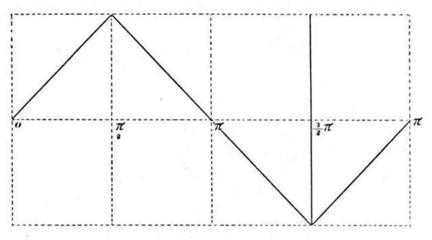
Since f(x) + f(x + 2!$ \pi !$/3) = const, for all values of x between x = 0 and x = !$ \pi !$/3, I infer that the curve f(x) may have any one of those forms, one of which is given in Fig. 7 (of the preceding paper). That is, the curve is symmetrical both with respect to the axis of x and also to the bisector A B and A' B' of the upper and lower maxima.
The curve given in Fig. 8 (of the preceding paper) would perhaps be aimed at in the construction of polyphasal dynamos. Its equation is
$$ f(x) = K \left( \sin x - \frac{1}{5^2} \sin 5x + \frac{1}{7^2} \sin 7x - \frac{1}{11^2} \sin 11x + \dots \right) $$
Let n = 4
Equation (2) gives
$$ \sum 2 a_m \sin m \left( x + \frac{\pi}{4} \right) \cos m \pi = c $$
and therefore
$$ \sum \frac{2 a_m}{m} \cos m \left( x + \frac{\pi}{4} \right) \cos m \frac{\pi}{4} = -c \left( x - \frac{\pi}{4} \right) $$ $$ = -\frac{c}{2} x - \frac{c}{2} x + \frac{c \pi}{4} $$
for all values of x between x = 0 and x = !$ \pi !$/2
The last equation can also be written
$$ \[ \sum \frac{a_m}{m} \cos m x - \sum \frac{a_m}{m} \sin \frac{m \pi}{2} \sin m x = -\frac{c}{2} x - \frac{c}{2} \left( x - \frac{\pi}{2} \right) \] $$
This relation enables us to determine the form of the component complex harmonic function f(x) which will fulfil all the conditions. It is easily seen that there is in this case just as in the case of three phases an infinitely numerous family of complex harmonics which will fulfil these conditions. The simplest harmonic is obtained by putting
$$ \sum_{m} \frac{a_m}{m} \cos m x = -\frac{c}{2} \left( x - \frac{\pi}{2} \right) $$ $$ \therefore \frac{a_m}{m} \cdot \frac{\pi}{4} = -\frac{c}{2} \int_{0}^{\pi/2} x \cos m x \, dx + \frac{c \pi}{4} \int_{0}^{\pi/2} \cos m x \, dx $$ $$ = \frac{c}{2 m^2} $$
and therefore
$$ a_m = \frac{2 c}{m \pi} $$
I conclude therefore that the harmonic
$$ f(x) = \frac{\sin x}{1^2} - \frac{\sin 3x}{3^2} + \frac{\sin 5x}{5^2} - \frac{\sin 7x}{7^2} + \dots ad\ infin. $$
fulfils all the conditions. Its form is given in Fig. 14. (It is only a special case of the curve, given in Fig. 13 of the preceding paper.)
The component harmonics fulfilling these conditions may be deduced similarly for any other value of n. But as the problem which I originally proposed to myself does not extend beyond these limits which I have just reached I prefer to postpone further considerations of the subject.
The character of these curves points out clearly the physical fact that it is an easy matter to construct three and four phase generators which will be capable of producing a constant resultant impressed E. M. F. Whether such generators will also be capable of producing a rotary magnetic field of practically constant intensity is a problem which I propose to discuss in a series of papers which will be presented shortly before the American Institute of Electrical Engineers.
Discussion
The Chairman [Prof. Thomson]: - You have heard the interesting and instructive paper by Dr. Pupin. I would say that it is perhaps the first exposition of some of the principles underlying this system of polyphasal transmission that I have seen, and I hope that the discussion may be indulged in by the members so that we may have some points cleared up by those conversant with the subject. It is now open for discussion.
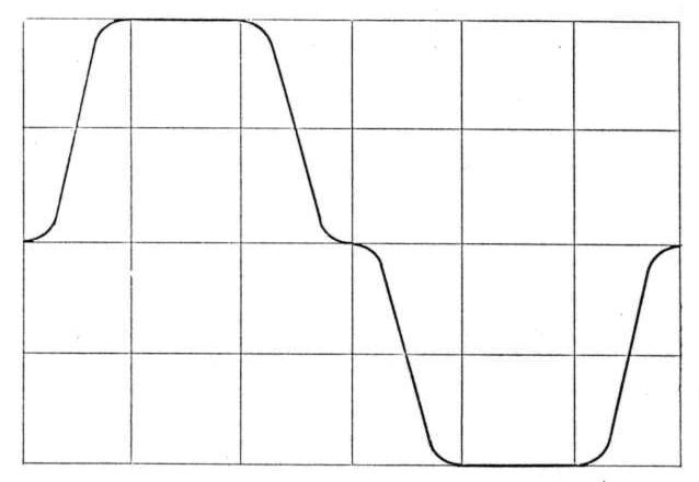
Mr. Chas. P. Steinmetz: - Having had the pleasure of hearing Prof. Pupin's paper at the New York Mathematical Society some days ago, I might be allowed to make the same remark I made there - that it would be perhaps more advisable to use a shape of the electromotive force similar to Fig. 7, than the shape in Fig. 8, because, as you see, in shape Fig. 8 the curve has a sharp corner, and even if we could produce waves of electromotive force that have sharp corners, it can hardly be expected that we can derive from such a sharp-cornered E. M. F. a current which, after being sent through step-down transformers, over lines of considerable electrostatic capacity, and again through step-down transformers into a motor of high self-induction, would still have retained this sharp-cornered shape. But the theory requires that the electric current in the motor has the shape given in Figs. 6 to 8. Even if the E. M. F. had the shape of Fig. 8, the current in such a highly inductive circuit would differ considerably, having lost the sharp corners, etc. Hence Fig. 8 would be less commendable. But the shape of Fig. 7 might easily be chosen, so that there would be no sharp corners, but a steady and continuous variation, as shown in Fig. 15.
Then, with regard to the equations of the currents x, y, z, on page 576, I wish to make a remark. As stated by Dr. Pupin, the complex harmonic of the electromotive force produces a current which is a complex harmonic too, and it is identically the same complex harmonic as long as the circuit has no self-induction and no capacity or, what amounts to the same, as long as self-induction and capacity have a certain ratio with each other. But as soon as the circuit has self-induction, the complex harmonic of current differs from the complex harmonic of electromotive force, and differs the more, the heavier the self-induction of the circuit is, by the decrease of the higher terms of this infinite series of simple harmonics which constitute the complex harmonic of electromotive force, these having a high self-induction; and therefore if we produce such a type of electromotive force and let it send a current through an inductive circuit, it will probably break to pieces entirely and show a current resembling a simple sine-wave as closely as one egg to another. In the equations for x, y, z, on page 576, as the condition that the shape of the current does not differ from the shape of the electromotive force, was found that the second term, m2p2 (L - M)2, can be neglected against the first term, R2. This means, in plain language, that the shape of the current-wave is the same as that of the E. M. F., if the self-induction of the circuit is negligible. For the first term, R, is the resistance; the second term, m p (L - M), is the inductance of the circuit.
Hence neglecting the second term means neglecting the inductance - that is, it means that the motor circuit has no self-induction. Now, anybody who ever tried to design an alternating motor, has found out to his disgust, generally, that the self-induction of such a motor, even under the most favorable conditions, is anything but negligible. Unfortunately, I could not get any data on these rotary motors, but on some other alternate current motors I can give data. In the Ganz and Company synchronous motor, the plant efficiency is claimed - by the manufacturers - to be 90 per cent. This unusually high plant efficiency, this unusually low retardation, might be explained by the fact that the motor is synchronous and the field fed by rectified alternate currents, that only the self-induction of the armature is in circuit, and the field adds no self-induction whatever. Furthermore, that the frequency used in those motors, 42 periods per second, is somewhat less than the one-third of the frequency of our American alternators. If this current were a complex harmonic we would have in the main wave 26 degrees retardation and 90 per cent. plant efficiency - that is, the intensity of the current would be 90 per cent. of that value it would have with no self-induction present. The second harmonic has only the plant efficiency of 72 percent.; the third harmonic of 7, the fourth of 47, the tenth only 20 per cent. - that is, is decreased to 20 per cent., while the first wave is decreased only to 90 per cent. Hence, even in a motor circuit of such unusually low self-induction, if a wave of shape Fig 8 is applied, it will come out entirely broken up, so I do not think that really the self-induction can be neglected. The more, as just the first term, R, is small, because we do not want to have the resistance of the circuit large, for the resistance determines the loss of power, and we do not want to have so much loss of power. We want to run motors with these currents. Indeed, if we run a motor from this alternating current, we get a counter-electromotive force in the motor, and to make these same equations hold we might represent this counter-electromotive force by apparent resistance. But in such a motor, the counter-electromotive force is not of equal phase with the current, but lags behind the current the more, the lighter the load, and will come nearer in phase to the phase of the current when we increase the load. Hence, the apparent inductance is not even a constant, but a variable of the circuit, and exceedingly variable, too. The inductance is small, almost nil, if the motor is at rest under full head of pressure. As soon as the motor starts, its self-induction increases, up to a value which corresponds to the load the motor is carrying, so that if the motor is heavily loaded the inductance is comparatively small, though very far from negligible, while, when the motor is running light, its self-induction increases to such a value as to almost entirely shut off the current.
Now I come to the consideration of this quantity (L - M). This quantity is really nothing but, or rather proportional to, that amount of magnetism, or that magnetism which constitutes the rotating magnet poles. So if the motor is at rest, heavy eddies in the short circuit armature-circulating coils, the useful magnetism is almost nil; almost no magnetism passes through the armature. Hence L is almost identical with M. The circuit has almost no self-induction. If the motor starts, runs with heavy load, then a certain amount of magnetism passes through the armature. L is different from M. L has increased, and we get a difference of phase of the current and a different shape of the current wave. Now, suppose the motor runs with almost no load, then the self-induction of the motor is very large and we can neglect R, the first term, entirely.
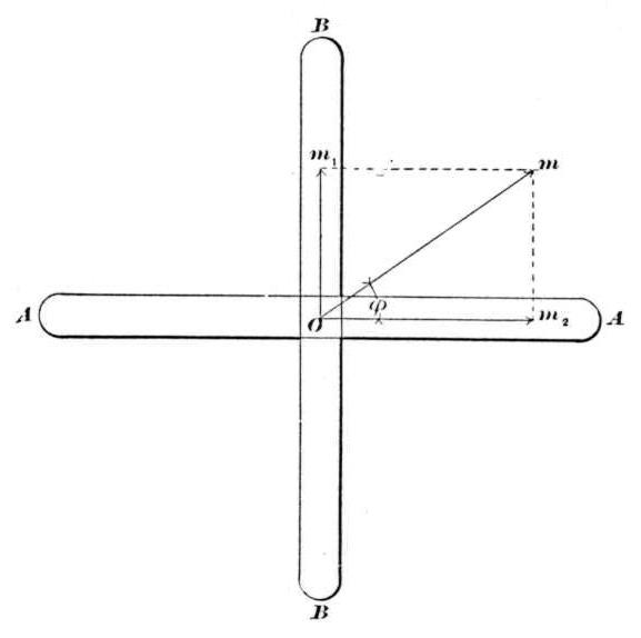
In this case the original shape of the electromotive force curve is entirely broken up and has changed into a somewhat harmonic shape. So I cannot think there is any hope to transfer any other shape of the curve but a simple harmonic through a circuit of heavy and very variable self-induction. That would be rather disappointing and very disagreeable for the builders of motors if the working of such rotary motors depended upon a certain shape of alternating current waves. Indeed, we all have heard and read half a dozen times - some of us even oftener - how bad and worthless the Tesla motor is, because there the fluctuations of the magnetism amount to, I believe, 41 per cent. and how grand and beautiful the improvements of Mr. Dolivo von Dobrowolsky are, because in his motor the fluctuations amount to only 14 percent., and if having heard and read something very often proves its truth, then it must certainly be true. At least this statement about the fluctuations of the intensity of the rotary magnetism seems generally to have been accepted as true. For I never heard any doubt expressed on the correctness of this fluctuation theory. And, nevertheless, in the very first publication of Ferraris on rotating magnet poles, in the very publication which introduced this rotary magnetism to the public years ago, it has been shown that if you sent two alternating currents, one lagging behind the other by one-quarter of a period, through two coils at right angles with each other, those two currents produced in the centre of those coils a magnetic field which revolves with constant strength and constant speed.
Let A in Fig. 16 represent the one, B the other one, of the two perpendicular coils, which are excited by two alternating currents of 90 degrees difference of phase. Then the magnetism produced by coil A at any time can be represented by the line,
$$ \overline{O m_2} = M \sin \varphi $$
The magnetism produced by coil B at the time t is
$$ \overline{O m_2} = M \cos \varphi $$
where
$$ \varphi = \frac{2\pi}{T} t $$
T being the time of one complete period.
These two magnetisms, $$ \overline{O m_1} $$ and $$ \overline{O m_2} $$ combine by the law of parallelogram, which as a consequence of the law of conservation of energy holds, to the resulting magnetism:
$$ \overline{O m} = M $$
of constant strength, at the phase:
$$ m_2 O m = \varphi = \frac{2\pi}{T} t $$
of constant velocity.
That means, the magnet poles revolve with constant strength and constant velocity, produced by true harmonic or sine-waves.1
Coming, now, to the conclusion, we see
1. It is possible to produce rotary magnetism of constant strength and constant velocity of rotation by means of true sine-waves.
2. It is hopeless to try to produce rotary magnetism of constant strength and velocity by means of a particular shape of the wave of E. M. F., because in a circuit of considerable and variable self-induction the shape of the current wave will differ in a considerable and a variable degree from the shape of the E. M. F. wave for any shape of the E. M. F. but the true harmonic or sine-wave.
3. Hence it is more advisable not to build the generators so that they produce that shape of E. M. F. which in a particular type of rotary motors will give magnetism of constant strength and velocity; but to build motors which will give magnetism of constant strength and velocity from true harmonic or sine-waves, as the only waves which can be transformed, transmitted through inductive and other circuits without changing their shape; to build the rotary motors for sine-waves, as the possibility has been shown by Ferraris, and as already in the oldest Tesla motors it evidently has been the aim of the designer. [Applause.]
Dr. Pupin: - Mr. Steinmetz went a little beyond the limits of this paper by talking about the motors. I said at the start that I was going to confine myself to the polyphasal generators and particularly to polyphasal generators which could under certain well defined conditions produce a rotary field of constant strength. I am going to consider in future the question of transformation and the question of rotating field used for driving a motor. Now, in the case that I considered, I simply had an iron ring surrounded by a set of coils and nothing else. I had no motor armature here. In this case, L - M could very easily be made small in comparison to R, the resistance, and therefore may be neglected. But you need not neglect it. If (L - M) is not negligible, then the magneto-motive force will vary, but its variation will be less than 14 per cent. How much less remains to be seen. I don't think that I can show it very well without entering fully into the discussion of the polyphasal motor and transformer. But this subject requires a carefully prepared paper to form a basis on which it can be advantageously discussed. If Mr. Steinmetz will have a little patience, I will promise to give him a chance to discuss these things also.
As far as the Ferraris contrivance is concerned, I never saw that paper to which Mr. Steinmetz refers. There must be a hitch in it, I think. Perhaps Mr. Steinmetz will exactly explain the contrivance, so that we can see the magnetic circuit and see whether his ideas are correct or not. I know a great many mistakes have been made on this very point of the magnetic circuit. Not enough attention was paid as to whether the magneto-motive forces worked in series or multiple arc, nor to the shape and distribution of the magnetic circuits. But still, I would like to know the exact form of the Ferraris motor and the magnetic circuits before I decide to comment upon it.
Mr. Steinmetz: - Ferraris built only a little toy, and his magnetic circuits, so far as I know, were completed in air, not in iron, though that hardly makes any difference. The only possible error there could be is the use of the law of parallelogram in combining E. M. F.'s acting in different directions upon a point, and this law of parallelogram, or polygon, is a consequence of the law of conservation of energy, and therefore its correctness can hardly be questioned. But as soon as you accept that, then the reasoning I have given here must be correct.2 So there is no possibility of any error if the whole phenomenon takes place in air. Suppose, now, the phenomenon does not take place in air, but in any other medium of constant magnetic conductivity, then you have exactly the same conditions. The air space between armature iron and field iron might introduce some discrepancy, though I hardly think so. But, then, the next problem would simply be how to shape the motor iron, how to distribute the wire coils, to get in the iron circuit separated by the air gap the same magnetic distribution as would take place without any iron in the air.
Dr. Pupin: - As you have heterogeneous media, you cannot have complete homogeneous magnetic circuits, and that is where the difficulty comes in. Your parallelogram of magnetizing forces will not apply here, and you are forced to be satisfied with the application of Ohm's law to magnetic circuits, which will not give you the result you claimed a little while ago.
Mr. Steinmetz: - Consider that wire coils of iron are closely embedded in iron, then there is no question that the same phenomenon takes place in the iron as in Ferraris's experiment in air. So the only problem would be how to shape the iron practically, to get rotary magnetism of constant strength and velocity from sine-waves.
This three-phase current system has been brought up the last time as something entirely new. I cannot agree with that in the least. For already in the old Tesla motor the three phases of current, only that in the three wires that go out from the central station the three currents have not a difference of phase of exactly 120 degrees, but two have a difference of 90 degrees, and either one of these two currents has with the third a difference of phase of 135 degrees. But if now the "Allgemeine Electricitæts Gesellschaft" transmits currents of less than 120 degrees difference of phase - well, then the Dobrowolsky system comes back exactly to the old three-wire system of Tesla, only that the motor is certainly built somewhat differently. But that does not matter. Mechanically, the motor is undoubtedly improved, for there are several years' time between the old Tesla three wire motor and the new German three phaser. Whether the latter shows any improvements in its principles, is a question which is anything but beyond doubt.
But in the new Dolivo von Dobrowolsky system of electric distribution, I really cannot see anything new but the mechanical construction of motors and generators. That it became so famous is, I think, entirely due to the success of the grand transmission of power over such an enormous distance as 116 miles, which cast a halo around everything that was used with this transmission, and so made the rotary motor famous; but, in reality, I think ordinary synchronous motors might just as well have been used, and would have worked just as successfully, so that the choice of the particular motor had nothing to do with the success of the power transmission.
Prof Thomson: - I should like to make some remarks upon the general subject of the paper. It is a matter to which I have given considerable thought. The subject is somewhat allied to the old Thomson-Houston arc machine. In fact, I remember long ago putting in a patent specification a machine connected so that it had not the three segment commutator but three rings, and it was rejected at the Patent Office on the ground that it was not an invention to put three rings on a three coil armature, any more than it was for any alternating current. But times have changed since then. [Laughter.] It seems to me some light would be thrown on the matter of this discussion by a few simple considerations. We will take the three coil in its simple form - symbols for it, Fig. 17. Now let us lead a wire, J, here, which would be a neutral wire. If we wrap that wire around a magnetic core, the effect should of course be the same or it should act the same as though these three wires, a, b, c, were wrapped around the magnetic core. So that if any fluctuations of magnetism were set up in this core by wrapping this neutral wire around the magnetic core, the same effect would be produced by wrapping these three wires around the magnetic core. That would show that no fluctuation might be expected in such a system. But there is another question that comes in just here. If we look into the manner of generating; if we take our armature and put on three coils, and have a magnetic field which magnetizes this armature core with a constant number of lines, a number of lines which does not change during the rotation - it is evident, then, that whatever actions occur in these coils will be accompanied by no fluctuations of magnetism. You cannot generate in a system of coils any difference of condition which is not expressed by the magnetic field in which it is generated. If the magnetic field is constant, then we have constancy of magnetism in the core. That is, we have no fluctuations. Now, it would seem to me, looking at it from this standpoint, that putting another armature in connection with these corresponding terminals and having a magnetic field for it of constant strength, we would have a rotating field produced in this second armature which would result in the rotation of the armature itself - that is, the tendency to rotate the field would turn the coils backward and this would seem to indicate that under certain conditions we can, with the ordinary arrangements, produce exactly what we want, steady rotative effect without magnetic fluctuations, which would go to bear out the Ferraris idea. Now, how far the production of a rotating magnetic field in the presence of a short circuited armature may modify these conditions, I have not investigated. It does seem to me, however, that in such case the remarks of Mr. Steinmetz are quite true, that we will have a large self-induction on a light load in such a motor and therefore a waste current, a leakage current corresponding to the leakage current in the transformer. Just how much it will be will of course depend on the general design and the proportions, and of course on the frequency of the alternations. I think the system demands that the frequencies shall be much less than we are accustomed to use in transformers for lighting. That the system will have a considerable application, I have not the slightest doubt. It will have a large application. Whether the best form of it is not to place two corresponding armatures in fields, or use synchronizing machines, is a question. I should say, reasoning at the start, that this is probably the chief merit of the system. We have the possibility of getting rid of commutation on high potential transmission of power by making corresponding machines and running corresponding armatures in the fields that are excited. Of course there is a great desire to get a motor which shall enable us to get rid of this constant excitation and which will give us the power of starting under load. The generator reversed and used as a motor, demands that in starting the generator shall also start, that the two machines shall come up together. I have, indeed, taken one Thomson-Houston arc machine and put on three rings and simply delivered the current by three rings to the armature of another machine, and it would start and run up to speed, having no load on it, at least no large load. It would get into synchronous rotation when the power delivered is, after exciting the field fully, considerable. I have constructed some small machines which are almost exactly like Fig. 10. There are six coils on the armature and a field excited separately. The field, by the way, rotates and the angle covered by the field poles is about what is covered there, Fig. 10. I have no indication at all of anything wrong with these machines. They work, we think, perfectly, and so far as the heat generated in the armature goes, it is remarkably small. It is no greater, from actual experiment, than one would expect from an ordinary machine with a commutator. In fact, it is probably less. Probably more fluctuation is introduced into the magnetism by the commutation than there would be in this case by the simple use of three coils without commutation. I would say further that I have never had much confidence in some of the reasoning of Mr. Dobrowolsky in relation to this matter. I have always thought that he was a little out in his argument. He has attempted to show how, by using three phased currents, he could get polyphasal currents from them, by winding the armature in a different way. It strikes me as nothing more than spreading that coil over a certain angle of the armature surface. This, of course, would prevent sudden sharp jumps in the field and might be useful and undoubtedly is useful in the perfection of a motor working upon a closed circuit armature. These matters of discussion would undoubtedly be best settled by a simple experimentation on the basis of what I indicated a little while ago. It may be that the very fact of the differences of composition of the wave may make a very great difference in the effect. We may not be called upon to reason upon fluctuations of magnetism due to sine curves when those sine curve currents are put in different angular positions. They may act, as in the Ferraris affair, to balance each other and oftentimes these considerations escape us.
I would say that there is another matter which probably ought to be taken into consideration. That is that a mass of iron does not always change its magnetism when you think it ought to. That is, it may hold up by its own inherent property of disregarding reversal - by hysteresis. This would tend, in fact, to hold the magnetism up rather than to allow it to suffer fluctuation. We know that in a closed circuit transformer it is necessary to put energy into the iron to cause it to drop its magnetism. It would tend to remain magnetized if we cut off the current at any portion of a wave, at least up to a certain point, and this would tend to help us out in this very matter of getting rid of fluctuations of magnetism, which of course would be a serious loss of energy in the case of large bodies of iron, the magnetism of which should be allowed to go up and down through large ranges. There is another matter, too, that comes in here. It is whether we get in the motor or in the machine a motion that is equal velocity - that is, whether it is an even pull all the way around, the sum of the magnetic lines being the same, or whether it is a jerky motion, a motion of difference of velocity. Of course, it will naturally be seen at once that unless we get a perfectly uniform flow, our efficiency could not be as high in the case of a fluctuating movement of the lines, and the lines which hesitate and then move forward and then hesitate again and then move forward, that would be only efficient in case the armature was negligible which, of course, could not be the case.
Mr. C. S. Bradley: - Did I understand Prof. Thomson to say that he thought the increase of the phasing by Dobrowolsky's plan was applicable especially to the closed armature?
Prof. Thomson: - No, I made no distinction between the kind of armatures. I simply say that Dobrowolsky's plan of multiplying the coils and connecting them up, did not differ very much, so far as I could see, from simply spreading those coils on the armature.
Mr. Bradley: - I understood you to say at the last that it applied especially to the closed circuit armature.
Prof. Thomson: - You mean by closed circuit armature, closed field and with connections taken out and around?
Mr. Bradley: - Yes.
Prof. Thomson: - No; I did not make such a distinction I should say that the closed circuit here would be just as effective forgetting the polyphasal circuit, provided the coils do not cover too large an angle.
Mr. Bradley: - It is a pretty difficult thing to make a test as to the efficiency of the different armatures. But I have always had an idea that the closed coil armature was exactly adapted to the carrying out of the three phase, because the currents can pass in more directions. There are more subdivisions than there are in the open circuit. With three open coils the position of each would determine its phase. But if it were completely closed and taken out at three points, there is a chance for two wires to operate and leave the third one nil, and the current has a chance to pass clear around the armature. That is, it will pass 120 degrees on one side and 240 degrees on the other side, making a multiple arc circuit. In other words, the closed coil armature carries out the plan that Dobrowolsky is trying to carry out, and does exactly what Dobrowolsky is trying to do by placing on the extra coils, without the extra coil.
Prof. Thomson: - I think that matter is made clear by considering the movement of the armature with respect to the lines. It does not seem to me to make very much difference what the coil is, providing the two armatures - suppose we take that as the typical system - the two machines are connected similarly. The movement of lines in one will be reproduced in the other, provided of course that the order of the connections and the symmetry of the apparatus are preserved.
Mr. Bradley: - I tested machines running that way. They were direct current machines altered to the three rings. I took them first and ran them as direct current machines. Then I had them changed and put three rings on each one and connected them up, and ran them together with the same power, and took off the same power, and I found the machines ran so nearly alike that I could not detect the difference. By the way, in your speaking of two machines, you have not at any time said motor and dynamo.
Prof. Thomson: - I, of course, meant motor and dynamo. It might interest the members for me to say that at one time, I think it was about 1882, I happened to have a three coil arc machine that had three rings on the shaft, and I discussed with my assistant, Mr. Rice, who is now superintendent of the Thomson-Houston works, this matter of connecting on three rings on two machines, and we found that the machines would work well as a means of transmitting power. But we had not facilities for building such apparatus in any quantity. However, it is an interesting reminiscence, as coming up at this time.
Mr. Steinmetz: - With regard to the spreading out of the coils on the armature, I think this makes very little if any difference in the shape of the wave, because if we had a coil of one single turn we would get a simple harmonic or sine wave where the maximum electromotive force = 1.414, the effective E. M. F. Now, only a few days ago I had occasion to draw the curve of electromotive force under exactly the opposite conditions, the most extreme case of spreading out the coils. A smooth continuous current armature changed into a bipolar alternator by connecting two opposite commutator bars with sliding rings, and I found as ratio between maximum E. M. F. and effective E. M. F.: 1.415; that is, exactly the same value as the sine wave gives. I found a wave somewhat similar to the sine wave, slightly different, with a tendency to the shape that Dr. Pupin showed us here in Fig. 8.
Prof. Thomson: - In making the remark as to the covering of the coils, I meant a motor with a closed circuit armature - not in relation to the generation of the current.
Mr. Kennelly: - This is a paper which, I think, has to be studied from two points of view. Like all mathematical papers, it presents two different aspects. We are face to face with a condition in the art of electrical distribution which is not only somewhat novel, but is also very intricate, and consequently any assistance, even of the most elementary description, which will enable us to fathom the mysteries of this difficult system of distribution, is one which should be only too gladly welcomed, I think, at the hands of this Institute. We have presented to us in this paper, a mathematical disquisition on the very simplest and most elementary type of the three phase generator, in which it is assumed that there is no armature reaction, no hysteresis and no eddy currents. Under those conditions, just as in the corresponding ideal transformer with constant coefficients, which has been called by some one the "phantom" transformer, that we all aspire so much after but so very seldom see - the fundamental operations of this particular machine are readily capable of being analyzed by the skill that has been presented in this paper. I think that we should be content to take one subject at a time, to consider that we have arrived at a position where modifications which will certainly present themselves by disturbing influences, will ultimately resolve themselves into this fundamental type, as they are lessened and removed. This is the starting point, so to speak, from which the various roads branch from the theoretical machine to the practical machine. I think, therefore, that while the paper gives us what may be called almost a little discovery, in its way, in practical mathematics, that it should be treated for its own value on the side of a mathematical essay, and not brought into the question of practical and everyday machines. We have the very remarkable fact that although the electromotive force which is capable of being produced by a complex condition of magnetic fields can be a uniform one, and while the currents which are set up by the electromotive force cannot possibly be the prototype of the electromotive force, graphically, when there is any self-induction in the circuit, yet that under the influence of mutual induction, that prototype may be restored. That is a beautiful conception, even although it may not have a very direct bearing on the practical side of the question. It seems to me that the practical issue of the question is not whether we can produce artificially and with considerable care a constant rotary magnetic field or a constant rotary electromotive force, for by theory we can produce any continuous curve; and any periodic wave can be established as the resultant of a number of simple harmonic waves, it only is a question of how many compounds we want. Sometimes we should want an infinite number. But however interesting that may be from the theoretical point of view, the next step in this difficult pathway which has been outlined here to-night, is not how to produce perfection, but how far differences from perfection will affect the practical result; not how necessary it may be to have a perfectly continuous field, but how far the fluctuations which will almost inevitably present themselves, will affect the efficiency and efficacy of these particular machines. At the same time, while we have to remember that the paper is a theoretical disquisition, it is also the first step towards practice, because theory follows ever slowly in the steps of practice, and it is in the direction of such a theory that we have to hope for the ultimate apprehension of all the difficulties before us.
Dr. Pupin: - The method which I have employed, as Mr. Kennelly remarked, is to go step by step from the ideal to the more and more practical, and see what the real difficulties are. Now, as long as we deal with simple harmonic waves, the question is exceedingly simple and is readily solved. The authorities on theoretical electrical engineering invariably consider the simple sine waves whenever they discuss the subject of periodically varying electric currents. Nobody has ever tackled the problem of complex harmonic waves. We really do not know what a complex harmonic wave will do. AVe can only guess at it. There are no quantitative relations. Now, I think that I have shown in this paper what a complex harmonic current wave will do in a particular case. I also propose to show before long what it will do in other practically important, but more complicated cases. Mr. Steinmetz points out that a combination of two simple sine waves can produce the same thing which I claim for the complex wave. But the correctness of his statement requires the employment of a homogeneous magnetic medium in which his two coils are to act. I would be very much obliged to him for the proof of the contrary.
The remark of Prof. Thomson with reference to the machine which he put on the blackboard, three coils rotating in a uniform field, has been answered in the very beginning of my paper. They will produce a constant rotary field, although the producing field, the exciting field, is constant. The relation of the coils with respect to the exciting fields, is continually varying, and the electromotive force produced in each one of those is a simple sine wave, and as long as we have simple sine waves and three phases, there will be a maximum variation of fourteen per cent., no matter what you do. Now wind the three wires on a piece of iron. The neutral wires will produce no magnetization. The three wires, if they are wound around the same coils in the same way will also produce no magnetization. So I do not think that the experiments suggested by Prof. Thomson could give us any record of any fluctuations in the rotary field. With respect to the production of that particular wave, Mr. Steinmetz remarked that it is impossible to produce anything like it. Of course, in nature there are no discontinuities. Nature hates discontinuity, and there are no absolutely discontinuous functions. Here, you see (Fig. 8), the tangent is continually constant at all points until the corner is reached, when the tangent suddenly becomes zero. This discontinuity is, of course, physically impossible, but in practice we can come as near to it as we choose to do, if we care to take the trouble. Of course, we would employ a practically discontinuous field. That is, you are in a place where there are lines of force, and suddenly you step into a place where there are practically no lines of force. Now, absolutely, that is impossible. But we can come as near as we choose to, by simply shaping the magnetic circuit in such a way that it will be nicely rounded and allow the lines of force of the magnetizing coils to follow it without getting too much out of their way. If you do that, then there will be practical discontinuities. Now, I have an electromagnet which will do that very nearly, where the lines of force of the magnetizing coils never deviate too suddenly from the magnetic circuit, and therefore there is very little leakage. I hope at some future time to show before the Institute, this electro-magnet. It is a very simple device. I do not say that I can produce that electro-magnet without sacrificing several practical advantages. But if it is only for experimental purposes, I do not care if I do sacrifice them. I dare say I will not rest until I get that electromotive force given in Fig. 8, plotted on paper from experimental results. But it is very difficult to do anything in New York in a hurry, because mechanicians will not attend to their orders when you wish them to, and you have to wait for them. As Mr. Kennely remarked, I do not think it is time yet to consider what will take place when we apply this rotary field to drive a motor, because I wish to limit the discussion to the limits of the paper.
Mr. Steinmetz: - With regard to this Ferraris scheme, I only wanted to show that under certain conditions a rotary field can be produced by sine waves of electric current. Suppose you have two equal coils at right angles with each other, entirely embedded in iron. The armature of the Pacinotti, or a similar type, with a very small clearance between armature iron and field iron, so small a clearance that the air reluctance can entirely be neglected against the reluctance of the iron - then you have exactly the conditions where you get from two sine waves of 90 degrees difference of phase, a system of magnet poles which revolve with constant intensity and constant velocity.
[Adjourned]
____________________________________________________________________________________________________________
1 Kapp: Alternate Current Machinery, page 82.
2 Exactly the same conclusion I find now given in Kapp, Alternate Current Machinery, page 82.
