
Nikola Tesla Articles
A Singular Confirmation of the Tesla Theory of Alternating Current Motors
Nothing is so strongly suggestive of the mysterious workings of the human intellect as the oft recurring fact of the independent discovery of a new scientific principle by two men in different parts of the world, and generally unknown to each other. And in no field has this fact of independent discovery been as apparent as in that of electrical science. We have now another instance to record. Right on the heels of the recent publication of Tesla's very interesting alternating current motor, comes the announcement, in London Industries, of a similar discovery by Prof. Galileo Ferraris, of Turin, of which we append a brief abstract:
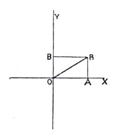
The principle on which the apparatus is based is exceedingly simple, and will be understood by reference to the accompanying sketches. Let in Fig. 1 the lines O A and O B represent in direction and magnitude the strength of two magnetic fields. The combined action of these fields on a unit pole, placed in the point O, would then be represented by the resultant O R. Instead of having two distinct fields, we have one resultant field, represented in direction and magnitude by this line. If both fields undergo periodic variations of the same period, the resultant field O R will also undergo a periodic variation, and the point R will traverse a curve, the form of which depends upon the precise manner in which the lines O A and O B change with the time. The fields O A and O B can be produced by two coils, having the lines O X and O Y respectively for their axes, and which coils are traversed by alternating currents of the same period. If the alternating currents may be expressed as sine functions of the time, and if there is an appreciable lag between the currents in the two coils, the point R describes an ellipse round O as center. In this case line O R, representing the resultant field, revolves round the center, O, the direction and magnitude of the resultant field changing at every instant. If, however, there is no lag between the two currents, that is to say, if they pass through zero simultaneously, the direction of the resultant field, O R, remains stationary, and the point R performs harmonic oscillation over the line R O and its prolongation with O as center. This may be considered as a special case of the ellipse where the latter has been flattened down to a mathematical line. Another special case occurs when the ellipse becomes a circle, and this must evidently take place when the lag between the two currents is 90°, when the coils are at right angles to each other, and when the component fields are equally strong. A metallic body suspended in the center of the two fields, and free to revolve, must evidently have a tendency to participate in the rotation of the resultant field.
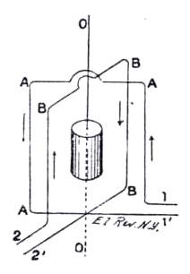
The application of this very simple principle will be clear from Fig. 2, in which the two coils are indicated by the rectangles A and B, the connections being made by the wires 1' and 2' respectively. When alternating currents are sent through these coils a resultant field is produced, which revolves round the line O O. In the center, between the coils, is suspended a small hollow cylinder of copper, and as the lines of the resultant field cut the metal Foucault currents are induced, and by the interaction of these induced currents and the revolving field the cylinder is set in rotation. The action is exactly the reverse of that occurring in the well-known experiment in which a copper disc is rapidly revolved below a compass needle, with the result that the compass needle is deflected on account of the induced currents in the copper disc, and ultimately caused to rotate with the copper disc.
Up to the present we have spoken of two distinct currents being required in the coils A and B, one lagging behind the other by a quarter period; and to perform the experiment we might employ an alternating current dynamo with two circuits in the armature, so arranged with regard to each other as to produce the desired lag. It is, however, possible to perform the experiment by using an ordinary alternating current machine with only one circuit on the armature, and to produce the second current by means of a transformer.
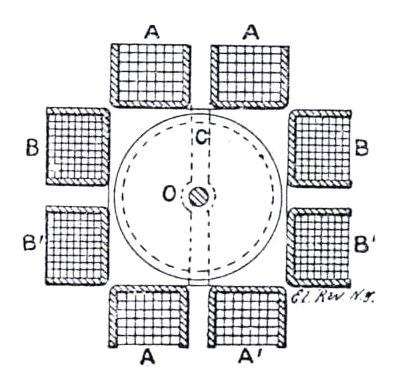
In the first experiment made by Professor Ferraris, a Gaulard & Gibbs transformer, with an equal number of turns in the primary and secondary coils, was used. In the primary circuit was included the coil A, consisting of a few turns of stout wire, whilst in the secondary circuit were included an adjustable and non-inductive resistance and the coil B, the latter consisting of many turns of fine wire. A small hollow copper cylinder was suspended on a thread in the center of the two coils, as shown in Fig. 2. If the current was sent through only one of the coils, the cylinder remained at rest; but if currents were sent through both coils, the cylinder immediately started to revolve, twisting the thread on which it was suspended. A reversing switch was inserted in the secondary circuit, and if the current through this circuit was inverted, the cylinder was immediately brought to rest, and started in the opposite direction. Professor Ferraris next substituted a small iron cylinder for the copper one, and found equal results; but when using an iron cylinder sufficiently large to nearly fill the place within the coils, the experiment did not succeed so well. He attributes this to the greater self-induction which the presence of iron in a large mass necessarily introduces into both circuits. Another experiment was made with a small iron cylinder, composed of a number of thin discs insulated from each other, and this experiment also succeeded. Foucault currents could not in this case be the cause of rotation, and Professor Ferraris thinks that the rotation is due to hysteresis. A large apparatus was then constructed which is indicated in our sketch, Fig. 3. In this case, the copper cylinder, which was mounted upon a horizontal axis in bearing, had a diameter of 3½ inches, and was 7 inches long, its weight being 11 pounds. This cylinder was closely surrounded by the primary and secondary coils wound upon wooden bobbins. To make room for the shaft each coil was in halves, the primary consisting of 96 turns of 77 mils. wire, both coupled in series, so as to produce the effect of a coil of 192 turns; the secondary consisting of 504 turns of 38 mils. wire, both being coupled in parallel, so as to produce the effect of 504 turns. The resistance of the primary coils was 7.12 and 6.63 ohms respectively, and that of the two secondary coils coupled in parallel was 3.43 ohms. In the secondary circuit was also inserted a rheostat without self induction, and the best results were obtained when the rheostat was set to between 15 and 18 ohms. A Gaulard & Gibbs transformer was used, giving 80 reversals per second. The copper cylinder began to revolve when the primary current was 5 amperes, and with higher currents the velocity could be increased to 900 revolutions per minute, and might have been still further increased but for the somewhat imperfect mechanical arrangements, which occasioned considerable vibrations. To the shaft was applied a small friction dynamometer, and the following table gives the work obtained on the brake by a primary current of 9 amperes at different speeds:
Revolutions per minute.... 262 400 546 653 722 770 772 900
Watts obtained on brake... 1.32 2.12 2.65 2.77 2.55 2.40 2.04 0
The maximum energy was obtained at 650 revolutions. Beyond that speed the energy decreased, which is attributed by Professor Ferraris to the imperfect mechanical arrangement of the apparatus, causing a considerable waste of power in vibrations. If it were not for this, the maximum energy would have been obtained at about 1,200 revolutions, whilst at 2,400 revolutions, which is the speed of the revolving resultant field, no energy at all could be obtained. Professor Ferraris suggests that this apparatus may be used for lecture purposes, and as a motor when the power required is small, and it may also be used as an electricity meter. The torque exerted by the revolving field upon the copper cylinder is proportional to the square of the current, and in order that the total number of revolutions performed in a given time may be an indication of the number of coulombs supplied, it is necessary to introduce some opposing force which varies with the square of the velocity. If this can be done, and if the friction of the journals can be sufficiently reduced, an ordinary counter attached to the axis would indicate the quantity of electricity supplied.
Mr. Tesla has produced a practical motor, while Prof. Ferraris has made only a lecture apparatus of no commercial value. The substantial honors belong to Mr. Tesla.