Nikola Tesla Articles
The Tesla Multiphase Motor
One of Tesla's Great Inventions
His Recent Improvement Therein - Features of the Harness Which Niagara Falls Will Wear
In some of the accounts of that remarkable achievement in Germany nearly three years ago of transmitting 300 horse-power in the form of electricity from the waterfall at Lauffen to Frankfort, 103 miles away, we read that it was a notable illustration of the "three-phase" system. Similar expressions are used regarding a plant in Southern California, set in operation last September and furnishing the city of Redlands with electricity generated at Mill Creek Canyon, nine miles away. The equipment for like purposes at Sewall's Dam, near Concord, N. H., is of the same class. We also run across the term "two-phase." It has been announced, for instance, that the enormous dynamos soon to be set in operation by Niagara Falls are to be adapted to the distribution of power on the "two-phase" plan. "Polyphase" and "multiphase" are other words coming into increasing use by scientific periodicals in mentioning existing or proposed electrical installations.
All this phraseology relates to a new system of converting an alternating current into power, invented by our young and gifted fellow-countryman, Nikola Tesla. Ferraris, an Italian, hit upon the same idea at almost the same time, but he did not develop it in a practical way; and Shallenberger, Elihu Thomson and others in this country, as well as various foreigners, have utilized it in some form. The plan has not yet come into extensive use, but in the near future it is destined to attract wide attention.
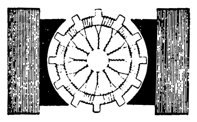
The special features of the Tesla system will be better understood, perhaps, if the reader will first recall the general arrangement of the types of motor now in use. These machines consist chiefly of a set of stationary electro-magnets, and between them, a rotating frame called the "armature." The whole or part of the current which drives the motor goes through the coils of copper wire in these magnets, and, by induction, magnetizes the soft iron cores. These are so fixed that the north pole of one points toward the south pole of the other, thus creating a "field of force" between them. For this reason, these magnets are called "field magnets." There are other coils of insulated copper wire on the armature, distributed around its periphery at regular intervals. Each one consists of many tightly wound turns, but in order to show the idea more clearly, our diagram exhibits only three or four to a coil. The ends of wire are brought down to the axle, and connected with separate bits of metal composing a "commutator." Two strips of copper or carbon, known as "brushes," and mounted so as to press gently on the commutator as the armature revolves, are the terminals of the wires which conduct the electricity generated at a distance, first into one and then to another of the armature coils. That is, one brush leads it in and the other leads it out. It will be seen that so long as the metal is running the field magnets are constantly energized, but the armature coils are only momentarily and successively influenced. A magnet will attract a wire or coil of wire which bears an electric current if that current be flowing in one direction, but it will repel that wire or coil if the current goes in the other direction. Now, in a motor the current is so guided into the armature coils that the latter are, in succession, drawn toward the poles of the field magnets, but as soon as each coil approaches as nearly as possible the current in it is reversed by the commutator, and then the coil is driven away. Both attraction and repulsion are so timed as to give motion to the revolving armature in the same direction. Meantime, the other magnet, on the other side of the machine, is co-operating in a similar manner. The armature, by the way, is a ring, not solid usually, but a lot of this iron plates insulated from each other, often perfected to allow ventilation, and bound into one by the encircling coils.
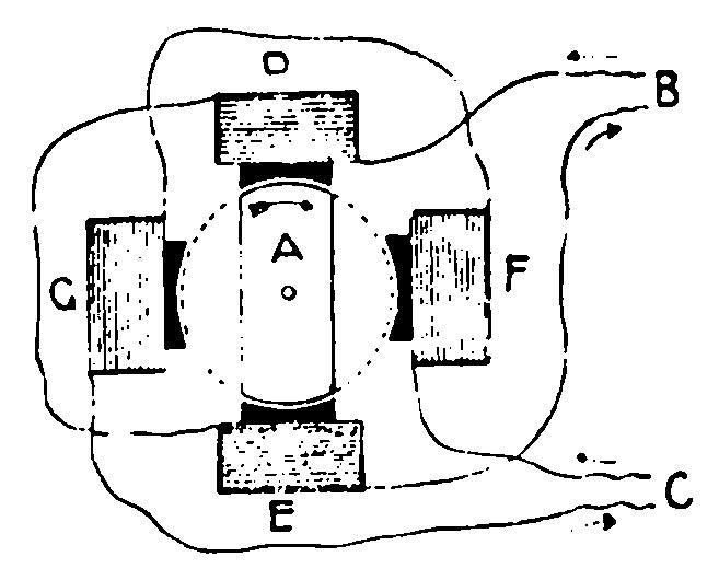
The principle which Mr. Tesla uses in his poly-phase motor is quite different. In its simplest form, his armatures is a mere bar or plate of magnetic iron, like A in our second diagram, mounted on a spindle so as to rotate. His "field of force," instead of being stationary, is made to go around in a circle, dragging the armature along as it goes. The field magnets do not actually move, however, but act in such a manner as to keep the centre of attraction shifting, progressively. In a "two-phase" motor, for instance, the current from the dynamo is divided so as to come in and go out first by one route, which is designated as B in our diagram, and then by another, marked C. The magnets D and E are included in the first circuit, and are simultaneously energized; and then, while the wave-like impulse is subsiding another comes in by the second circuit and acts upon the other pair of magnets. Let us suppose that at starting the current first comes in by the route B, and makes the end of D facing the centre of our circle a "north" pole, and the corresponding end of E a "south" pole. We will also suppose that the armature has a slight magnetic predisposition of its own, which impels the end that is uppermost in our diagram to seek a north pole, wherever it can find one. At the outset, then, it will be drawn to D, while E will similarly attract the other end. If, now, the current is let into the circuit C, and makes a north pole at F, the armature will feel two attractions, and swing so as to be half way between those magnets. But the wave in D is dying out, and that in F is rising; so that the latter magnet is soon in supreme control, and the armature moves to a position at a right angle with its first one. Meantime, G has a "south" polarity, and attracts the other end of the armature. When the current next flows through the wires at B, its direction has been reversed, as it is an "alternating" current, so that D is a "south" pole, and E is a "north" pole. Hence E coaxes the arrow-marked end of the armature at first part of the way and then all of the way from F; and we have secured half a rotation. The other half is obtained by the same general method; and the armature is soon spinning at great speed. In a three-phase motor of this pattern there are six magnets instead of four: and there are three separate circuits instead of two.
Mr. Tesla found, after a little, that a circular disk would retain its polarity as well as a bar, and hence ceased to slice off the sides of his armature, as he did at first. He and his imitators have also tried many modifications of form for the field magnets, while retaining the principle of moving the field around in a circle. In its latest form the armature is a cylinder, not a disk. A few turns of heavy copper wire are distributed about it, wound from end to end, to intensify the magnetism of the iron inside.
It was not long before this ingenious inventor discovered that three wires would do the work of four for a two-phase motor. It seemed necessary to have two separate ones for supply purposes, but not two for the return currents. The three-phase motor is also, at present, operated by three wires, two of which are made to carry the three sets of inflowing waves, since no two circuits are in full service at once. Mr. Tesla has even devised a way - several ways, in fact - by which the two (or three) currents may be separated, not at the dynamo which generates them, but close to the motor; so that the latter may, if desirable, be used on an ordinary two-wire circuit. It has been intimated, however, that the Niagara electrical output will be distributed by the four-wire system.
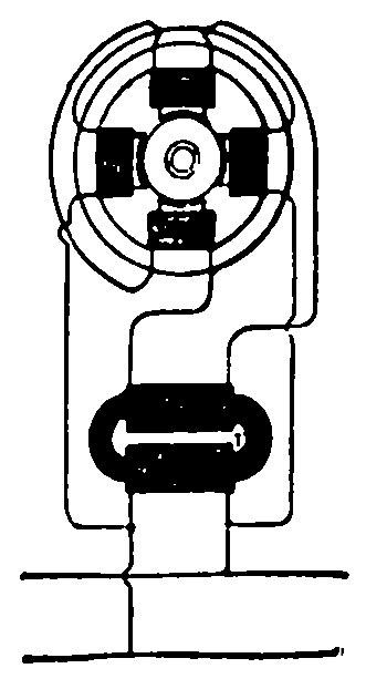
One of Mr. Tesla's means for effecting separation on the site of the motor is a transformer, or induction coil. This piece of apparatus consists of two coils of copper wire so insulated and combined that the primary current passing through one excites a secondary current in the other. It should be borne in mind that the current used with polyphase motors is not a continuous but an alternating one; that is, it is made up of a series of minute oscillations in opposite directions. Thence the secondary, as well as the primary, alternates. But the impulses of the secondary lag an exceedingly small fraction of time behind those of the primary; and that lag can be magnetized if desired. Thence, Mr. Tesla is able to energize the coil of his two-phase motor with the primary current and the other with the secondary. Our third diagram indicates the arrangement of the apparatus. He has devised several other schemes for dividing the current at the place where it is used, instead of where it is generated.
Almost all the electric motors running to-day, on trolley cars, in workshops and mines and to operate elevators, are driven by a direct or continuous current, by a system similar to that described in the first part of this article. There are plenty of alternating current dynamos, which generate electricity for lighting and other purposes, but very few alternating current motors. Various difficulties have stood in the way of making one which would work as satisfactorily as those of the other type. There are several reasons, however, why it is desirable to have a good motor capable of being operated by an alternating current. A plant generating the latter for lighting purposes, for instance, could then supply electricity for power also. And in the application of this form of force to a vast variety of industries, in the near future, adaptability to all uses will be an important economic factor. Furthermore, the alternating current has advantages over the direct when it comes to production on a large scale and transmission to great distances.
One serious objection to the alternating motor, when run by a single current, has been that it was not self-starting. Other power was required to give the rotations of the armature a frequency equivalent to that of the waves of the energizing current before it would run alone. Possibly this may be overcome, some day, with a "single-phase" machine; but the multiphase motor is already a self-starter. The polyphase plan also gets rid of the commutator and brushes, which, in motors (as in dynamos), are liable to emit dangerous sparks. A disadvantage attaching to other motors, including those of the "direct" type, is that the armature coils become overheated, and "burn out," when more work than the machine is adapted to perform is imposed upon it. No such ruinous effect is experienced by the multiphase motor; if overloaded, it merely stops. For this reason and for others, it is said, less skillful workmen are needed to operate such motors.
