
Nikola Tesla Articles
The Tesla Steam Turbine (October 12, 1911)
A novel design of steam turbine was mentioned before a local meeting of the National Electric Light Association in New York City, on May 15, 1911, by Mr. Nikola Tesla, whose name has become famous in connection with the rotating magnetic field and other alternating-current developments. Several different types of power apparatus, both driving and driven, embodying the underlying principle of this turbine design have now been built and tested in the Tesla laboratories, including a turbine which has been running at the Waterside Station of the New York Edison Company for several months. The general results of this early work have recently been made public by Mr. Tesla.
The following outline of the designs and the underlying principle running through them all has been made after a conversation with Mr. Tesla and a study of the apparatus. The fundamental principle underlying these several designs appears to be broadly applicable to apparatus wherein a fluid moves some device or the device causes the fluid to move. This includes hydraulic, steam and internal combustion motors, hydraulic and air pumps, etc.
The study of this most interesting line of designs may be approached through the case of either prime movers or driven devices. For the purposes of this article it is perhaps simpler to consider first a pump for a fluid like air, gas, vapor, or liquid. Fig. 1 shows, more or less diagrammatically, a rotary pump in which a series of smooth, flat disks revolves in a casing, with a volute delivery passage. The disks are fastened to a driving shaft but have central openings which serve as inlets for the fluid. On rotating the shaft and disks, the fluid film in contact with the disks is set in motion, even with perfectly smooth disks, on account of the molecular adhesion between disk and fluid. The fluid between disks is also dragged along by the molecular attraction between particles of the fluid (viscosity). The motion of each point of the disk being circular, it is evident that the particles of fluid receive impelling forces which are always tangential to the circular paths. The successive points on the disk that impel given particles of fluid are at increasing distances from the center. The fluid being mechanically unconstrained by walls or vanes except in an axial direction is free to travel in spiral paths from the axis to the periphery.
The fluid, in traversing the space from inlet to periphery, may follow a long spiral of several turns or a short one of part of a turn, depending on the quantity of fluid that is allowed to escape from the outlet. With unrestricted flow from the casing, there is little resistance to flow in a radial direction (that is from the backing up and development of pressure), and the tangential slip between disk and fluid is large. The pressure in the casing depends on the velocity with which the particles of fluid leave the periphery of the disk; the maximum pressure with the exit throttled is then proportional to the speed of the disks, the velocity head being converted to pressure head in the volute passage of the casing. The power absorbed is proportional to the square of the slip.
To one seeing such a piece of apparatus in action for the first time, the capacity of a small machine is surprising, especially in the absence of all vanes and projections of every sort which have heretofore been deemed necessary to force the fluid along. A moment's consideration, however, shows that the whole surface of each disk is effective in impelling the fluid along (solely by molecular drag), and the useful surfaces may be made very great in a machine of modest dimensions, in direct contrast with other analogous apparatus where only the relatively small area of buckets, blades, or other projections is effective.
Consideration also shows that any buckets or projecting parts that a disk might carry would constrain the fluid to travel in paths less natural or free, with the consequent development of impact and eddy friction which may be expected to decrease the efficiency over that of simple disks depending for their hold on the fluid only on natural molecular forces. In the case of the Tesla disks, the particles of fluid may be mentally pictured as rolling along on their spiral paths in orderly procession, held to the disks by some gravitation or force; whereas in the case of a disk with projections, the fluid would be pushed and crowded along by impact, with consequent disturbances.
It has been found, as theory would indicate, that the quantity of fluid discharged off the disks is proportional to the area of the disks; that is, the capacity or such machines increases nearly directly with their length along the shaft and about as the square of their diameter, the discrepancies arising naturally from the casing not having impelling surface but adding to the diameter and length of the machine.
The spacing of the disks in such a machine would depend on the conditions under which it had to operate - increasing with the viscosity and diameter and decreasing with the allowable slip. The aim of the designer would be to deliver the fluid from the disks at not much below peripheral speed under normal load conditions. When limitations of practical design would prevent the securing of desired pressures with one simple set of disks, the multiplication of stages is easily accomplished. The fluid then would pass from the exit passages of one stage to the inlet of a second, and so on.
The operations of a pump, as above described, are in general reversible for the production of power from a fluid moving with considerable velocity or under pressure. If a fluid under pressure, but of low velocity, enters the casing of the device shown in Fig. 1 in order to flow along the volute of decreasing cross-section and through the inter-disk spaces to what is now the outlet, it must constantly accelerate, converting its pressure head to velocity head. This moving fluid will exert a pull on the disks on account of molecular adhesion and viscosity. If the shaft were blocked so that it could not rotate, the particles of fluid would take short spiral paths from the volute to the outlet.
If the disks are allowed to rotate, however, the particles of fluid in contact with the disks would be subjected to a force preventing travel along the shortest spirals to the outset. The resultant of the centrifugal force exerted by the disk and that coming from the velocity of the steam constrains the fluid then to follow a longer spiral path. This reminds one of the counter E. M. F. developed in the armature windings of an electric motor opposing the impressed voltage.
It is evident that the torque developed by the disk increases with the difference in peripheral velocity of the disk and of the fluid in contact. As in the analogous case of the pump, the torque rises as the square of the slip. When the shaft runs free, without load, the speed rises and the centrifugal counter force on the fluid traveling in very long spirals (almost concentric circles) would cause the casing pressure to rise nearly to the supply pressure, the difference being only that required to do the work of supplying energy losses.
Such a prime mover would give its maximum output at about 50% average slip, but the maximum efficiency would come with a comparatively small slip, the actual figure depending upon the fluid employed, on the working conditions, and on the mechanical limitations of design.


The greatest interest in the Tesla design, as outlined above, probably centers in its application to a heat motor, such as the Tesla steam turbine. While a device like Fig. 1 would operate with steam, it probably would be advisable for obvious reasons to modify the mechanical features - for instance, to suppress the volute passage in the casing, coming down to the simple construction indicated in Fig. 2.
If the steam is expanded in a diverging nozzle it may be expanded over any of the usual ranges of pressure drop, the heat energy then being converted into kinetic energy. The high velocity steam escaping from the nozzle is caused to impinge tangentially on the edges of the disks. In order to escape, it has to take a spiral path from the periphery of the disks to the center openings. The velocity energy of the steam is utilized through the molecular drag on the surface of the disks. With such a nozzle it is seen that the machine is essentially of the so-called "Impulse" type of turbine. The arrangement shown in Fig. 2 has a very simple and convenient means of reversing, it merely being necessary to provide a duplicate nozzle discharging against the opposite diameter of the disks and in the opposite direction. When the machine is at rest or running slowly, as in starting, steam takes a short path from the nozzle to the exhaust and develops a comparatively large torque, since this would be proportional to the square of the difference in velocity of steam and disk. As the machine speeds up, the difference in velocity between steam and disks decreases and the centrifugal forces tend to lengthen the spiral path, so that a given quantity of steam may make several revolutions before finally passing out the exhaust.
It is not necessary, however, to expand the steam before it reaches the disks, and in place of the nozzles shown there may be simple ports. The machine then apparently will operate as a reaction type of turbine, the steam expanding as it flows in its path from port to exhaust. The expanding steam might develop a slight reactive thrust against the disk, but it would depend probably more for its influence on the peculiar action of increasing the velocity of the steam in small increments as it flows along; and absorbing the kinetic energy as fast as developed, in driving the disk.
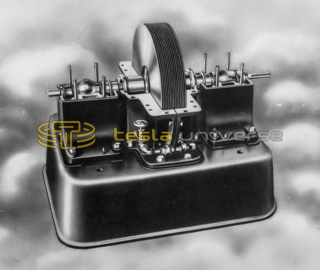
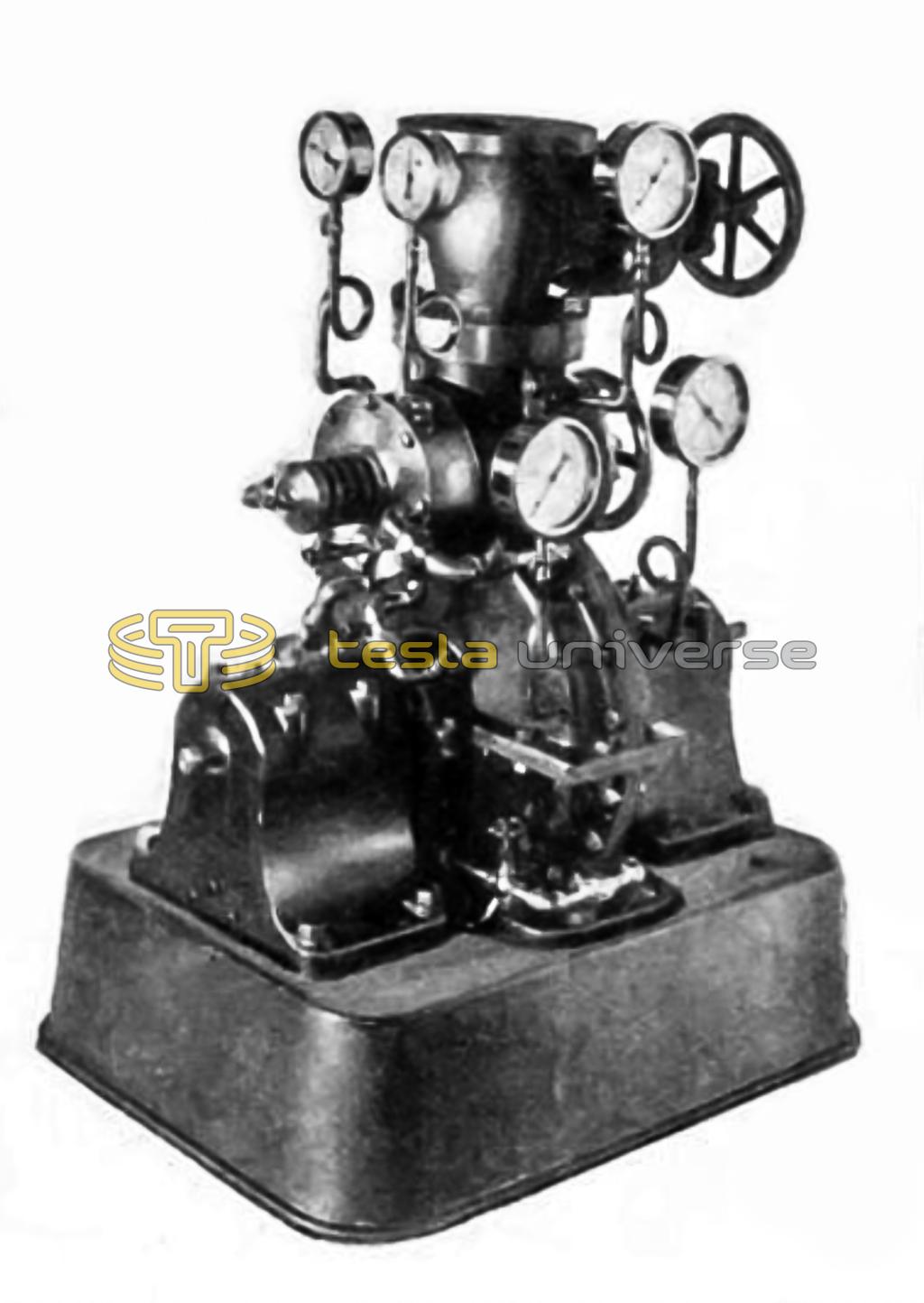
In Figs. 3 and 4, a steam turbine tested at the Waterside Station of the New York Edison Company is shown. The rotor consists of 25 disks, 18 inches in diameter. The assembled unit, Fig. 3, occupies a floor space some 20 x 35 ins. and it stands some 5 ft. high. The numerous gages seen in Fig. 3 were attached for test purposes. With steam at 125 lbs. gage and exhausting to atmosphere, 200 HP. was developed with a speed of 9,000 r. p. m. The steam consumption under these conditions was about 38 lbs. per HP.-hr. Mr. Tesla states that with moderate superheat and the degree of vacuum ordinarily obtainable in a turbine plant, the consumption can be reduced to 10 or 12 lbs. per HP.-hr. The weight of the unit as shown was about 400 lbs., giving a unit weight of 2 lbs. per HP.
Through refinements in design in addition to the increase of capacity secured with superheat and vacuum, Mr. Tesla expects that the weight may be reduced to as little as ¼-lb. per HP. capacity and still allow of designs which will have rotational speeds low enough for direct connecting to the majority of services.
One of the interesting possibilities of the design of turbine shown is that of self-regulation. It has already been shown how the counter pressure due to the rotation of the disks amounted nearly to that of the impressed fluid when running idle. Since the centrifugal head increases as the square of the number of revolutions, and as with available materials great peripheral velocities of the disks are possible, a turbine may be designed which will not run away, the peripheral speed being limited to that value which corresponds to the maximum velocity of the fluid which can be developed.
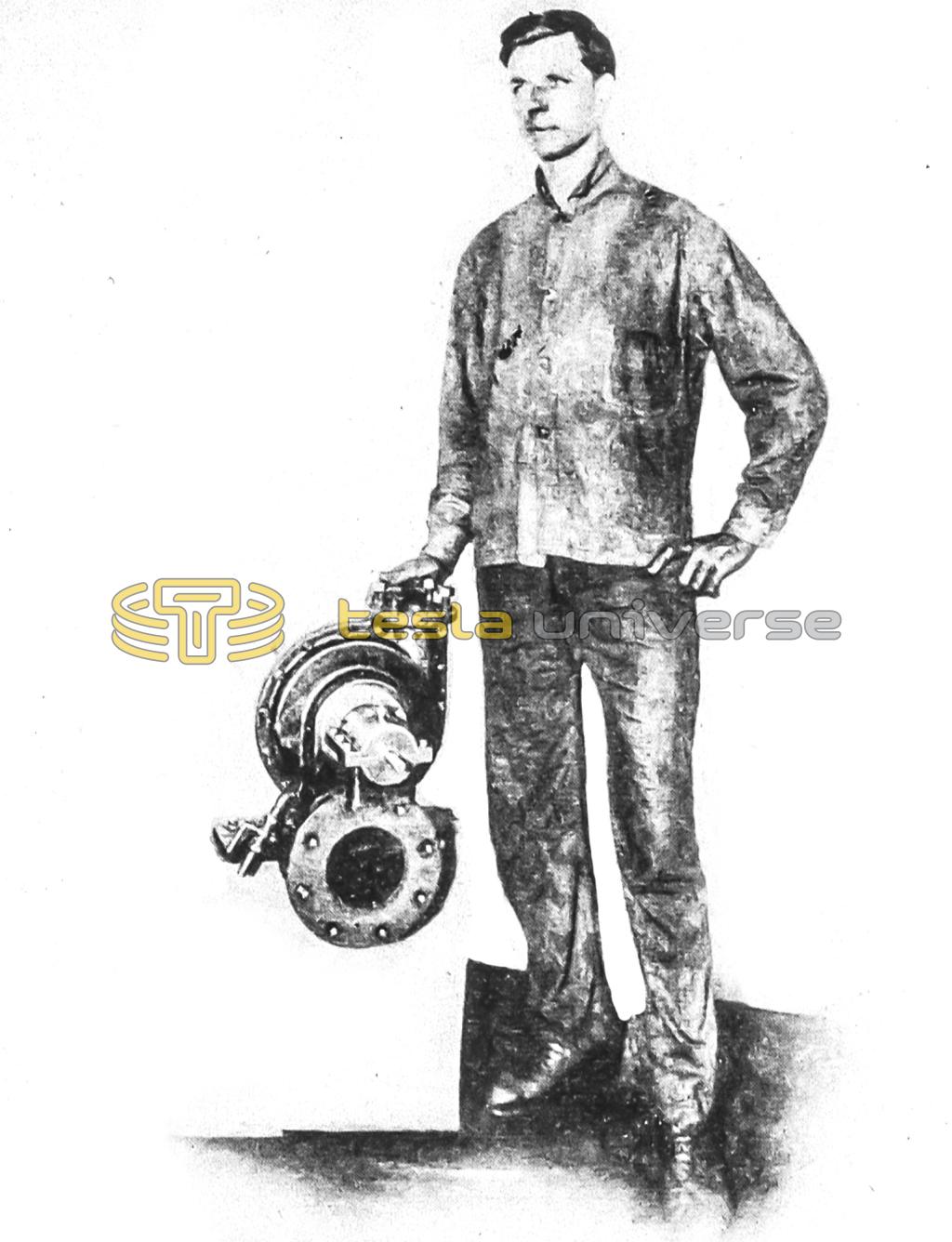
The main principle of design may be use for an internal-combustion motor. The small machine shown in Fig. 5 has been operated with gaseous fuel burned in an auxiliary chamber and the products of combustion cooled by injecting steam or water spray. This gives a mixture of superheated steam and gases which leave the combustion chamber under high pressure, but reduced in temperature so that they may be led directly to the disks, serving the place of steam from a boiler. The machine shown developed 110 HP., and it is stated that only the small sized shaft prevented pushing the load higher. The products of combustion instead of being cooled by the formation of superheated steam may be expanded in an insulated nozzle, the temperature falling with the reduction in pressure and the increase in velocity. At the exit of the nozzle, the temperature could be sufficiently reduced so that the gases could be caused to impinge on the disks without injuring them.
* For early statements of these developments see "Electrical Review and Western Electrician," Sept. 9 and 30, 1911; "The Scientific American," Sept. 30. 1911.
