
Nikola Tesla Articles
Tesla's Alternative Geometry Coil
Introduction
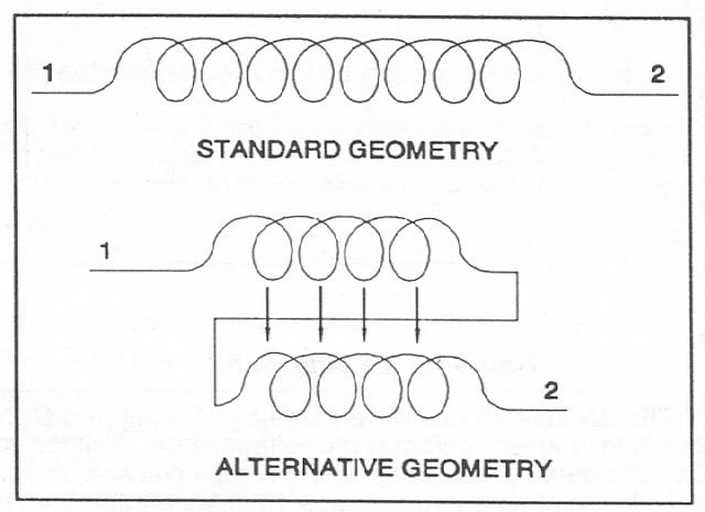
Tesla's patent "Coil for Electromagnets," #512,340, states that the double series winding, whether as a flat spiral or conventional helix, eliminates self-induction and stores more energy than a single wound coil at resonance. Because such coils are not covered in textbooks, measurements were made on two similar coils of the same diameter and with the same number of turns. One coil was single wound, the other with Tesla's alternative bifilar geometry.
Before considering the measurements, the concept of self-inductance will be examined. Though a common technical term at the turn of the century, the concept has been supplanted in modern usage.
Self-Inductance
In the patent it is noted that in ac systems "the self-induction of the coils.... does operate disadvantageously by giving rise to false currents which often reduce what is known as the commercial efficiency of the apparatus...." The aim of the patent design is to overcome the effect of self-induction.
The nature of self-induction, and, by that, the method used to overcome it can be clarified with the help of a handbook. Basic Electricity, prepared by the Bureau of Naval Personnel notes:
...when an alternating voltage is applied to an inductor, the inductor reacts in such a way as to oppose alternating current flow. This opposition is thus referred to in general as an inductive reactance. The amount of opposition exhibited by a coil depends on the magnitude of its self-induced voltage, Eind. The effective value of this self-induced voltage, or counter emf in volts is
Eind = 2!$ \pi !$fLI.
When a current is set up in a conductor, or field established around such a conductor, an adjacent conductor has induced in it a current, or field, of opposite value that opposes the flow of the of the original current.
If considered in the context of Ohm's Law, it can be seen that the self-induced voltage is just another way of expressing opposition to current flow than the more familiar inductive reactance which expresses the same relationship in terms of ohms:
E = IR and R = E/I as
Eind = 2!$ \pi !$fLI and XL = Eind/I or
XL = 2!$ \pi !$fL.
In more contemporary terms, then, the patent design aims at eliminating inductive reactance - creating a coil in which a current can "pass through it with no other opposition than that of ohmic resistance, or, in other words, as though it possessed no self-induction."
Capacity and Energy Storage
The patent notes that in ordinary coils "the capacity to counteract the self-induction" is small because the voltage difference between the turns is small - "so while they are in a sense condensers, they possess but very small capacity..." The increase in capacity, then, that counters self-induction is an increase of the capacitance between turns of the coil. In turn, the capacitance between turns is increased by increasing the voltage difference between the individual turns of the coil.
It can be seen that if a potential of 100 volts is established between points 1 & 2 on each coil that in a standard coil the potential difference will be divided into a number of equipotential steps equal to the number of turns in the coil. In the bifilar coil, the potential is "seen" through the turns of the first strand and, then, in the turns of the second strand. In the bifilar, then, the potential difference over the full coil is divided between only two equipotential steps.
The example used in the patent is 100 volts divided into 1000 equipotential steps equal to the number of turns in the standard coil. The bifilar's 100 volts is divided into 2 equipotential steps. As the patent cites, the difference of potential between each turn in the standard coil is 100/1000 = 0.1 volts and the difference between turns of the bifilar is 100/2 = 50 volts.
Again, according to the patent, if the turns in the coil are considered as a condenser then the relative amount of energy stored in each type of coil can be calculated by the equation for energy storage for a capacitor in which energy is proportional to the square of the voltage. In the patent's case the difference is 250,000 times the energy storage for the bifilar.
502/0.12 = 2500/0.01 = 250,000
It may be, though, that the patent understated the energy storage effect of the bifilar design. At resonance it may be the case that the first strand of the bifilar is seeing the impressed 100 volts positive but the second strand is experiencing an induced voltage of equal value but opposite sign. Using the values in the patent, strand 1 would be at+100 volts and strand 2 at - 100 volts making the voltage difference between turns 200 volts. If that is the case the energy storage difference between the two types of coils would be:
2002/0.12 = 4 x 10⁴/0.01 = 4 x 10⁶.
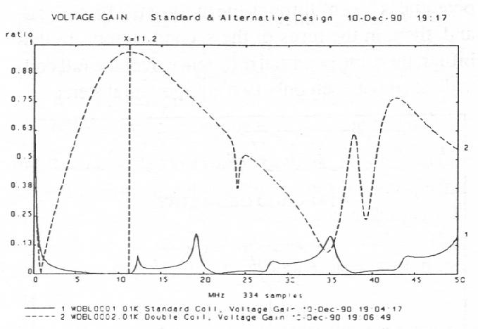
This value seems to be supported by the following voltage measurement made on the two coils. The maximum voltage across the bifilar coil at 11.2 MHz was 965 x 10-3 volts and across the standard coil 672 x 10-6 volts. V2DBL/V2STD 2 x 10⁶.*
Impedance
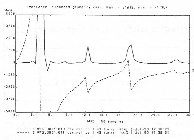
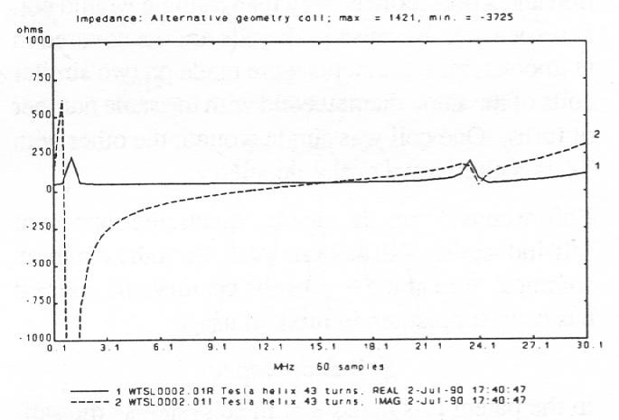
Greater voltage gain is matched by the lower impedance of the double wound coil. That the graph of the bifilar impedance measurement is not linear, indicating a measurement of inductive reactance, is due to the additional capacitance obtained by using the double winding. With the double winding the capacitance is significantly greater than a standard coil and causes the coil to react as a LRC circuit when tested on the network analyzer.
The imaginary impedance curve on the chart, then, does not represent XL but rather:
Z = r2 + (XL-XC)2.
One thing that can be concluded from the impedance measurement of the LRC network is that the inductance, which is directly proportional to XL, does not decrease as the impedance of the network decreases.
Additionally, it appears that Z is reduced to ohmic resistance over a range of frequencies.
Measurements confirm the Tesla's assertion that his coil design creates a better electromagnet. Magnetic flux is a function of Volts x seconds, thus, as voltage increases, so will the magnetic flux:
ФB = V x s
In that the inductance of a coil is a measure of magnetic flux per unit of current, L = ФB/I, and because the voltage increases due to the geometry of the winding and the current increases due to the lowered effects of self-inductance, the ratio between V/I remains the same. This means that a bifilar coil measured at X millihenries retains that value under load.
The advantage that this coil possesses is that as the stronger magnetic field builds and collapses it would transfer a greater amount of energy to a load (increase the coil current) instead of transforming the current to heat:
I = ФB/L = Vxs/L
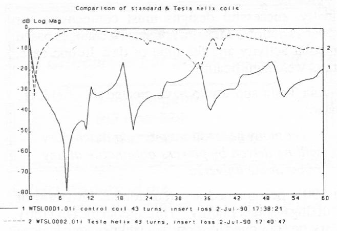
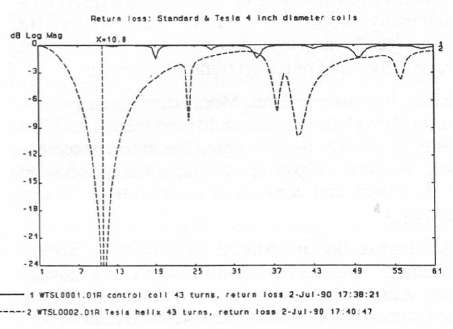
That is, for the same inductance value as a standard coil, the bifilar design allows a greater amount of the current put into the coil reach a device attached to the coil. This is also seen in the lower insertion and higher return loss at resonance.
*NOTE: Measurements were made by M. King and O. Nichelson at Eyring, Inc. M. King modified Eyring's data acquisition program to display the voltage ratios. Voltage values were taken from the network analyzer screen and are to be considered preliminary. Comparing a coil at a resonant point with one at non-resonant point may not establish the likelihood of an energy storage 16 times greater than the 250,000:1 claimed in the patent, but it does illustrate a marked difference in response for two similar coils.
