Nikola Tesla Articles
Tesla's High Potential Transformer
In his experiments involving high potentials Mr. Nikola Tesla has for some time past made use of a special form of induction coil, and in a recent patent issued to him he describes several forms specially adapted to be used in connection with a system of high potential power transmission. To accomplish the desired object Mr. Tesla employs an induction coil or transformer in which the primary and secondary coils are wound in such manner that the convolutions of the conductor of the latter will be farther removed from the primary as the liability of injury from the effects of potential increases, the terminal or point of highest potential being the most remote, and so that between adjacent convolutions there shall be the least possible difference of potential.
The type of coil in which the last named features are present is the flat spiral, and this form Mr. Tesla generally employs, winding the primary on the outside of the secondary and taking off the current from the latter at the center or inner end of the spiral.
In constructing his improved transformers Mr. Tesla employs a length of secondary which is approximately one-quarter of the wave length of the electrical disturbance in the circuit including the secondary coil, based on the velocity of propagation of electrical disturbances through such circuit, or, in general, of such length that the potential at the terminal of the secondary which is the more remote from the primary shall be at its maximum. In using these coils the inventor connects one end of the secondary, or that in proximity to the primary, to earth, and in order to more effectually provide against injury to persons or to the apparatus he also connects it with the primary.
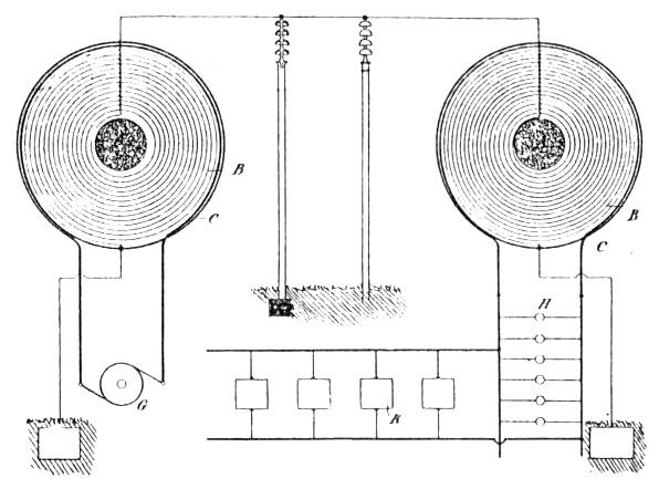
The accompanying diagram, Fig. 1, illustrates the plan of winding and connection employed in constructing the improved coils and the manner of using them for the transmission of energy over long distances.
A designates a core, which may be magnetic, around which the coil B is wound in spiral form. C is the primary, which is wound around in proximity to the secondary. One terminal of the latter will be at the center of the spiral coil, and from this the current is taken to line. The other terminal of the secondary is connected to earth and also to the primary.
When two coils are used in a transmission system in which the currents are raised to a high potential and then reconverted to a lower potential, the receiving transformer will be constructed and connected in the same manner as the first — that is to say, the inner or center end of what corresponds to the secondary of the first will be connected to line and the other end to earth and to the local circuit or that which corresponds to the primary of the first. In such case also the line wire should be supported in such manner as to avoid loss by the current jumping from line to objects in its vicinity and in contact with earth — as, for example, by means of long insulators, mounted, preferably, on metal poles, so that in case of leakage from the line it will pass harmlessly to earth. In Fig. 1, where such a system is illustrated, a dynamo G is represented as supplying the primary of the sending or "step-up" transformer and lamps H and motors K are shown as connected with the corresponding circuit of the receiving or "step-down" transformer.
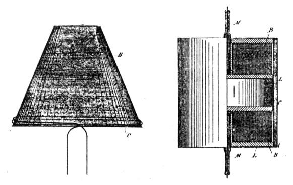
Instead of winding the coils in the form of a flat spiral the secondary may be wound on a support in the shape of a frustum of a cone and the primary wound around its base, as shown in Fig. 2.
In practice for apparatus designed for ordinary usage the coil is usually constructed on the plan illustrated in Fig. 3. In this figure L L are spools of insulating material upon which the secondary is wound — in the present case, however, in two sections, so as to constitute really two secondaries. The primary C is a spirally-wound flat strip surrounding both secondaries B. The inner terminals of the secondaries are led out through tubes of insulating material M, while the other or outside terminals are connected with the primary.
The length of the secondary coil B or of each secondary coil when two are used, as in Fig. 3, is, as before stated, approximately one-quarter of the wave length of the electrical disturbance in the secondary circuit, based on the velocity of propagation of the electrical disturbance through the coil itself and the circuit with which it is designed to be used — that is to say, if the rate at which a current traverses the circuit, including the coil, be 185,000 miles per second, then a frequency of 925 per second would maintain 925 stationary waves in a circuit 185,000 miles long, and each wave length would be 200 miles in length. For such a frequency Mr. Tesla would use a secondary 50 miles in length, so that at one terminal the potential would be zero and at the other maximum.
Coils of this character, according to Mr. Tesla, have several important advantages. As the potential increases with the number of turns the difference of potential between adjacent turns is comparatively small, and hence a very high potential, impracticable with ordinary coils, may be successfully maintained. As the secondary is electrically connected with the primary the latter will be at substantially the same potential as the adjacent portions of the secondary, so that there will be no tendency for sparks to jump from one to the other and destroy the insulation. Moreover, as both primary and secondary are grounded and the line-terminal of the coil carried and protected to a point remote from the apparatus the danger of a discharge through the body of a person handling or approaching the apparatus is reduced to a minimum.