Nikola Tesla Articles
Tesla's New Alternating Motors
For some time past Mr. Nikola Tesla, whose previous work in alternating current motors is well known, has been engaged upon the study of these machines in order to develop efficient methods for operating them on two wires instead of three, and still without the use of a commutator.
The general principle upon which these machines are designed is based on the well-known fact that if a magnetic core, even if laminated, be wound with a coil and a current be sent through, the magnetization of the entire core does not immediately ensue, the magnetizing effect not being exhibited in all parts simultaneously. This Mr. Tesla attributes to the fact that the action of the current is to energize first those laminae or parts of the core nearest the surface and adjacent to the exciting coil, and from thence the action progresses towards the interior. A certain interval of time, therefore, elapses between the manifestation of magnetism in the external and the internal sections or layers of the core.
If the core be thin or of small mass this effect may be inappreciable, but in the case of a thick core, or even of a comparatively thin one, if the number of alternation be very great, the time interval occurring between the manifestations of magnetism in the interior of the core and in those parts adjacent to the coil is more marked, and in the construction of such apparatus as motors which are designed to be run by alternating currents, Mr. Tesla has found it desirable, and even necessary, to give due consideration to this phenomenon and to make special provisions in order to obviate its consequences.
On the other hand, by taking advantage of this very action or effect, and, by rendering it more pronounced, Mr. Tesla utilizes it in the operation of motors in general. This he effects by constructing a field in which the parts of the core that exhibit at different intervals of time the magnetic effect imparted to them by alternating currents in an energizing coil are so placed with relation to a rotating armature as to exert thereon their attractive effect successively in the order of their magnetization. By this means there is secured a result similar to that which Mr. Tesla has heretofore attained in the previous types of his motor, in which, by means of one or more alternating currents, he produces a rotation or progression of the magnetic poles or points of maximum attraction of the field of force.
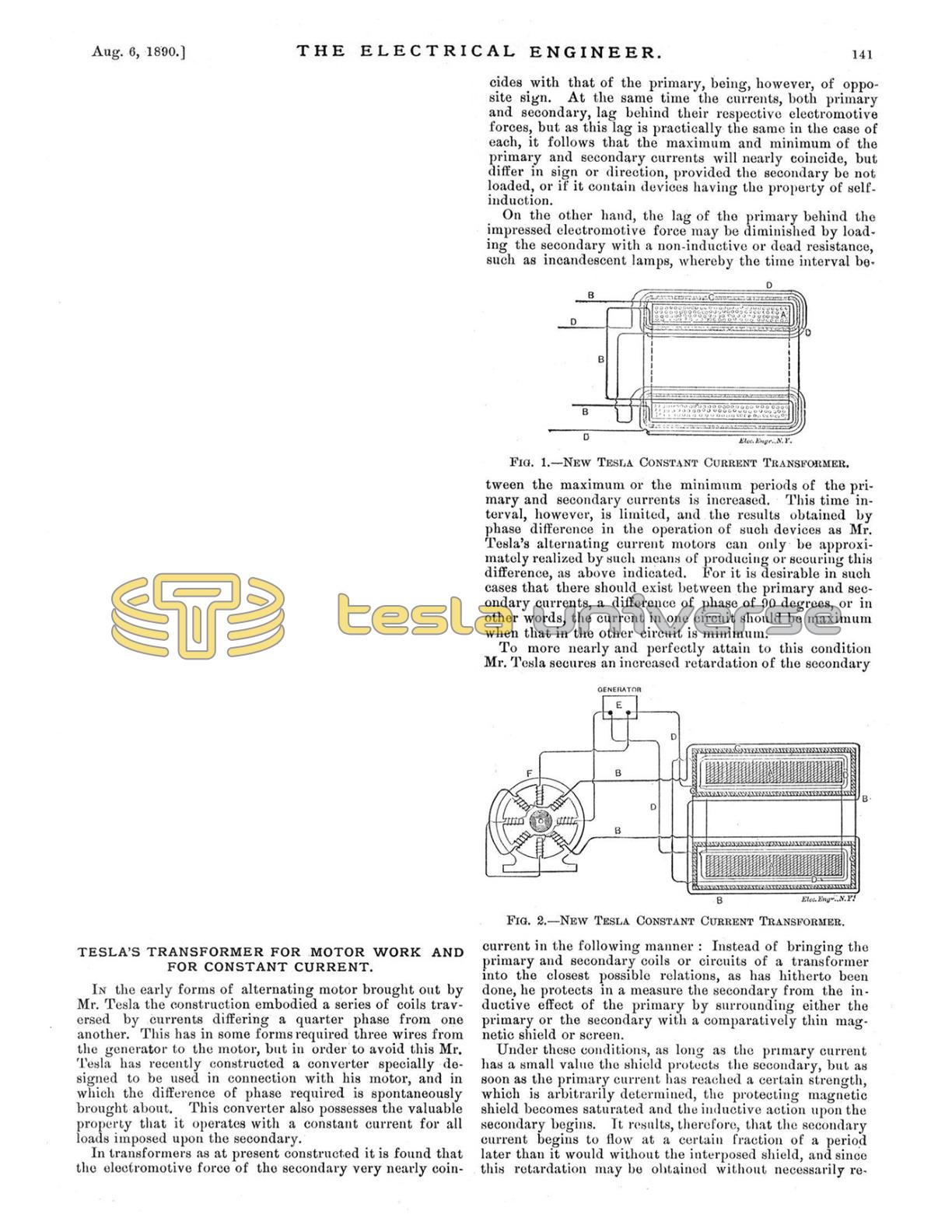
The general principle involved in the action above mentioned is illustrated in the simple motor shown in Fig. 1. Here X represents a large iron core composed of a number of sheets or laminae of soft iron or steel. Surrounding this core is a coil, Y, which is connected with a source, E, of rapidly varying currents.
Let us consider now the magnetic conditions existing in this core at any point, as b, at or near the centre, and any other point, as a, nearer the surface. According to Mr. Tesla, when a current impulse is started in the magnetizing coil, Y, the section, at a, being close to the coil, is immediately energized, while the section, at b, which, to use a convenient expression, is "protected" by the intervening sections or layers between a and b, does not at once exhibit its magnetism. However, as the magnetization of a increases, b becomes also affected, reaching finally its maximum strength some time later than a.

Upon the weakening of the current the magnetization of a first diminishes, while b still exhibits its maximum strength, but the continued weakening of a is attended by a subsequent weakening of b. Assuming the current to be an alternating one, a will now be reversed while b still continues of the polarity first imparted. This action continues, the magnetic condition of b following that of a in the manner above described.
If an armature, for instance, a simple disk mounted to rotate freely on an axis, be brought into proximity to the core, a movement of rotation will be imparted to the disk, the direction depending upon its position relatively to the core, the tendency being to turn the position of the disk nearest to the core from a to b, as indicated in Fig. 1.
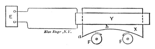
This action or principle of operation has been embodied in a practicable form of motor, which is illustrated in Fig. 2. Here A represents a circular frame of iron, from diametrically opposite points of the interior of which the cores project.
Each core is composed of three main parts B, B and C, and they are similarly made with a straight portion e, around which the energizing coil is wound, a curved arm or extension c and an inwardly projecting pole d.


Each core is made of two parts B B, with their polar extensions reaching in one direction and a part C between the other two and with its polar extension reaching in the opposite direction. These cores are wound with coils D, which are connected in the same circuit either in parallel or series and supplied with an alternating current by a generator E represented diagramatically. Between the cores or their polar extensions is mounted an armature F wound with magnetizing coils G that are closed upon themselves, similar to those in the older types of Mr. Tesla's motors.
The operation of the motor is as follows: When a current impulse or alternation is sent through the coils D, the sections B B of the cores being on the surface, and in close proximity to the coils, are immediately energized. The sections C, on the other hand, are protected from the magnetizing influence of the coil by the interposed layers of iron B B.
As the magnetism of B B increases, however, the sections C are also energized, but they do not attain their maximum strength until a certain time subsequent to the exhibition by the sections B B of their maximum.
Upon the weakening of the current the magnetic strength of B B first diminishes while the sections C have still their maximum strength; but as B B continue to weaken, the interior sections are similarly weakened.
B B may then begin to exhibit an opposite polarity, which is followed later by a similar change on C, and this action continues.
B B and C may, therefore, be considered as separate field magnets, being extended so as to act on the armature in the most efficient positions, and the effect is similar to that in Mr. Tesla's other forms of motor, viz., a rotation or progression of the maximum points of the field of force. Any armature, such, for instance, as a disc mounted in this field, would rotate from the pole first, to exhibit its magnetism to that which exhibits it later.
In following out the ideas stated above, Mr. Tesla has applied them to a class of motors in which two or more sets of energizing magnets are employed and in which by artificial means a certain interval of time is made to elapse between the respective maximum or minimum periods of their magnetic attraction or effect. This has already been applied to the operation of Mr. Tesla's three-wire motors. In the present instance Mr. Tesla employs a motor with two sets of energizing or field magnets, each wound with coils connected with a source of alternating currents, but forming two separate paths or circuits. The magnets of one set are protected to a certain extent from the energizing action of the current by means of a magnetic shield or screen of laminated iron interposed between the magnet and its energizing coil.
The shield is properly adapted to the conditions of particular cases so as to shield or protect the main core from magnetization until it has become itself saturated and no longer capable of containing all the lines of force produced by the current. By this means it will be seen that the energizing action begins in the protected set of magnets, a certain arbitrarily determined period of time later than in the other, and that by this means a practically economical difference of magnetic phase may readily be secured.
The nature and operation of this motor will be readily understood by reference to the accompanying illustration.
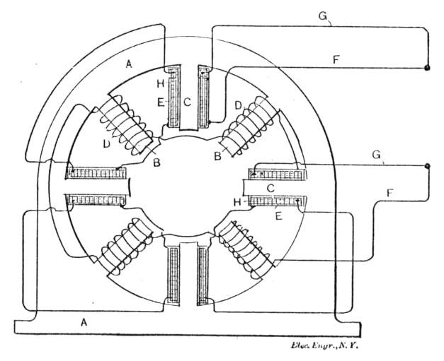
The engraving, Fig. 4, shows the simplest form of this type of machine. The cores B form one set of magnets and are energized by coils D, while the cores C, forming the other set, are energized by coils E, and the coils are connected in series with one another, in two derived or branched circuits F G respectively.
Each coil E, it will be noted, is surrounded by a magnetic shield H, which is composed of an annealed insulated or oxidized iron wire wound on the coils in the manner indicated, so as to form a closed magnetic circuit around the coils and between the same and the magnetic cores C.
Between the pole pieces or cores B C is mounted the armature of the closed-circuit coil type.
The operation resulting from this arrangement is as follows: If a current impulse be directed through the two circuits of the motor, it will quickly energize the cores B, but not so the cores C, for the reason that in passing through the coils E there is encountered the influence of the closed magnetic circuits formed by the shields H. The first effect is to effectively retard the current impulse in circuit G, while at the same time the proportion of current which does pass does not magnetize the cores C, which are shielded or screened by the shields H.
As the increasing electromotive force then urges more current through the coils E, the iron wire H becomes magnetically saturated and incapable of carrying all the lines of force, and hence ceases to protect the cores C, which become magnetized, developing their maximum effect after an interval of time subsequent to the similar manifestation of strength in the other set of magnets, the extent of which may be arbitrarily determined by the thickness of the shield H, and other well known conditions.
From the above it will be seen that the apparatus or device acts in two ways. First, by retarding the current, and second by retarding the magnetization of one set of cores, from which its effectiveness will readily be seen.
Many modifications of the principle here embodied have been made by Mr. Tesla, one only more of which we may notice here. This is illustrated in Fig. 5, and is similar in all respects to that above described, except that the iron wire H, which is wrapped around the coils E, is in this case connected in series with the coils D. The iron wire coils are connected and wound so as to have little or no self-induction, and, being added to the resistance of the circuit F, the action of the current in that circuit will be accellerated while in the other circuit G it will be retarded.
Still another type of motor constructed by Mr. Tesla is one with a field magnet having two sets of poles or inwardly projecting cores and placed side by side so as practically to form two fields of force, and alternately arranged, that is to say, with the poles of one set or field opposite the spaces between the other. The free ends of one set of poles are then connected by means of laminated iron bands or bridge pieces of considerably smaller cross-section than the cores themselves, so that the cores all form parts of complete magnetic circuits.
When the coils on each set of magnets are connected in multiple circuits from an alternating machine electromotive forces are set up in each circuit simultaneously, but the coils on the magnetically bridged or shunted cores will have, by reason of the closed magnetic circuits, a high self-induction which retards the current, permitting at the beginning of each impulse but little current to pass. On the other hand, no such opposition being encountered in the other set of coils, the current passes freely through them, magnetizing the poles on which they are wound.
As soon, however, as the laminated bridges become saturated and incapable of carrying all the lines of force, which the rising electromotive force, and consequently increased current, produce, free poles are developed at the ends of the cores, which, acting in conjunction with the others, produce rotation of the armature.
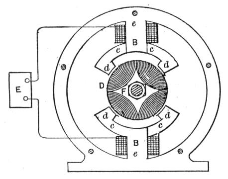
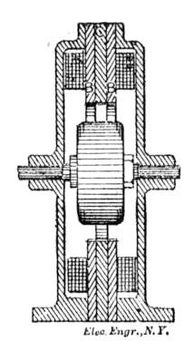
The construction by which this is accomplished is shown in the accompanying engravings, Figs. 6 and 7.
The frame of the motor A, is built up of sheets of iron punched out to the desired shape and bolted together with insulation between the sheets. When complete the frame makes a field magnet with inwardly projecting pole pieces B and C. To adapt them to the requirements of this particular case, these pole pieces are out of line with one another, those marked B surrounding one end of the armature, and the others C the opposite end, and they are arranged alternately; that is to say, the pole pieces of one are set in line with the spaces between those of the other sets.
The pole pieces C are connected or shunted by bridge pieces E.
The coils F and G are connected in series, respectively, in two circuits which are branches of a circuit from an alternating machine, and they are so wound that the circuit of coils G will have a higher self-induction than the other circuit or branch.
The function of the shunts or bridges E, is that they shall form with the cores C a closed magnetic circuit for a current up to a predetermined strength, so that when saturated by such current and unable to carry more lines of force than such a current produces, they will, to no further appreciable extent, interfere with the development by a stronger current of free magnetic poles at the ends of the cores C.
In such a motor the current is so retarded in the coils G and the manifestation of the free magnetism in the poles C is delayed beyond the periods of maximum magnetic effect in poles B. The result is that a strong torque is produced and the motor operates with approximately the power developed in a motor of this kind energized by independently generated currents differing by a full quarter phase.