Nikola Tesla Articles
Tesla's Transformer for Motor Work and for Constant Current
In the early forms of alternating motor brought out by Mr. Tesla the construction embodied a series of coils traversed by currents differing a quarter phase from one another. This has in some forms required three wires from the generator to the motor, but in order to avoid this Mr. Tesla has recently constructed a converter specially designed to be used in connection with his motor, and in which the difference of phase required is spontaneously brought about. This converter also possesses the valuable property that it operates with a constant current for all loads imposed upon the secondary.
In transformers as at present constructed it is found that the electromotive force of the secondary very nearly coincides with that of the primary, being, however, of opposite sign. At the same time the currents, both primary and secondary, lag behind their respective electromotive forces, but as this lag is practically the same in the case of each, it follows that the maximum and minimum of the primary and secondary currents will nearly coincide, but differ in sign or direction, provided the secondary be not loaded, or if it contain devices having the property of self-induction.
On the other hand, the lag of the primary behind the impressed electromotive force may be diminished by loading the secondary with a non-inductive or dead resistance, such as incandescent lamps, whereby the time interval between the maximum or the minimum periods of the primary and secondary currents is increased. This time interval, however, is limited, and the results obtained by phase difference in the operation of such devices as Mr. Tesla's alternating current motors can only be approximately realized by such means of producing or securing this difference, as above indicated. For it is desirable in such cases that there should exist between the primary and secondary currents, a difference of phase of 90 degrees, or in other words, the current in one circuit should be maximum when that in the other circuit is minimum.
To more nearly and perfectly attain to this condition Mr. Tesla secures an increased retardation of the secondary current in the following manner: Instead of bringing the primary and secondary coils or circuits of a transformer into the closest possible relations, as has hitherto been done, he protects in a measure the secondary from the inductive effect of the primary by surrounding either the primary or the secondary with a comparatively thin magnetic shield or screen.
Under these conditions, as long as the primary current has a small value the shield protects the secondary, but as soon as the primary current has reached a certain strength, which is arbitrarily determined, the protecting magnetic shield becomes saturated and the inductive action upon the secondary begins. Tt results, therefore, that the secondary current begins to flow at a certain fraction of a period later than it would without the interposed shield, and since this retardation may be obtained without necessarily retarding the primary current also, an additional lag is secured and the time interval between the maximum or minimum periods of the primary and secondary currents is increased.
Mr. Tesla has also discovered that such a transformer, by properly proportioning its elements, be made to yield a constant current at all loads.
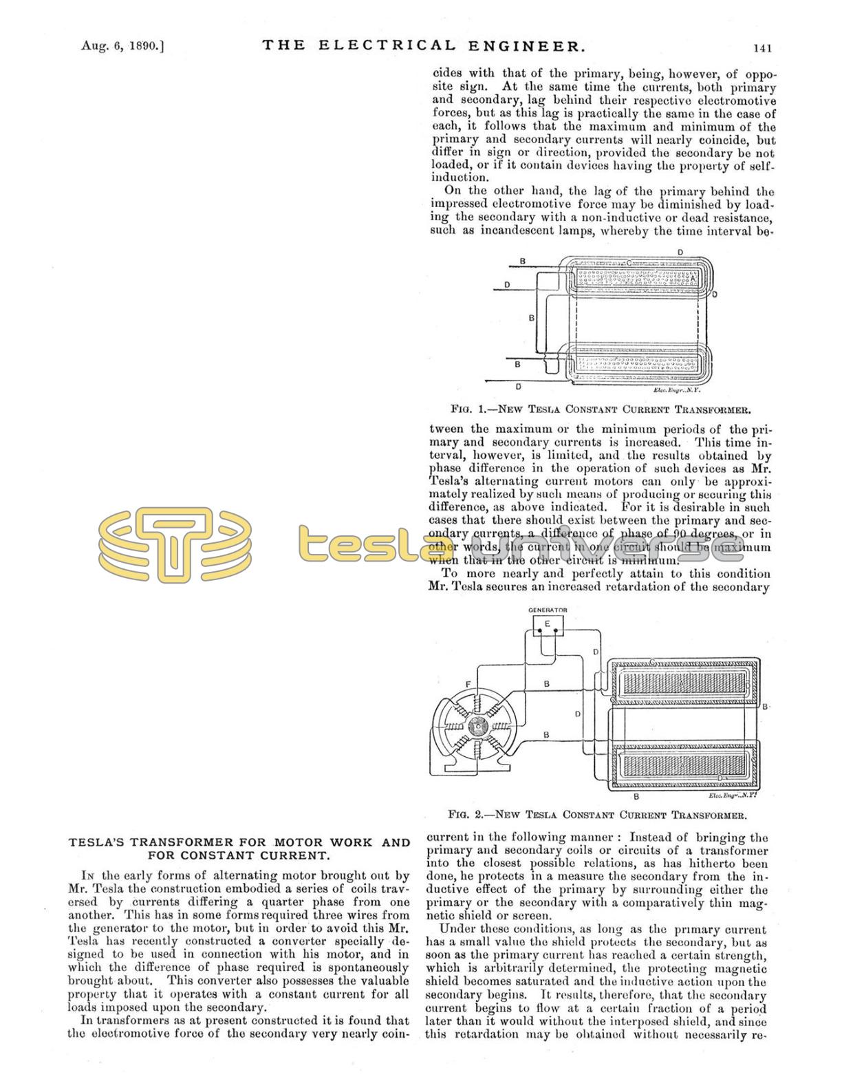
In the accompanying illustrations, Fig. 1 is a cross-section of a transformer embodying the above idea.
A A is the main core of the transformer composed of a ring of annealed iron wire. Upon this core is wound the secondary circuit B B. This latter is then covered with a layer of annealed iron wires C C, wound in a direction at right angles to the secondary coil. Over the whole is then wound the primary coil D D.
From the nature of this construction it will be obvious that as long as the shield formed by the wires C is below magnetic saturation, the secondary coil or circuit is effectually protected or shielded from the inductive influence of the primary.
When the strength of the primary reaches a certain value, the shield C, becoming saturated, ceases to protect the secondary from inductive action and current is in consequence developed therein. For similar reasons, when the primary current weakens, the weakening of the secondary is retarded to the same extent.
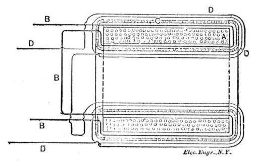
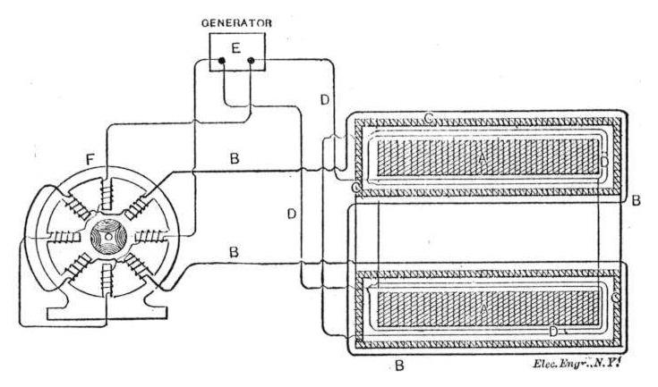
In the engraving, Fig. 2, the core A is built up of insulated iron plates or disks. The primary circuit D is wound next to core A. Over this is applied the shield C, which in this case is made up of thin plates of iron properly insulated and surrounding the primary, forming a closed magnetic circuit. The secondary B is wound over the shield C.
In Fig. 2, the primary of the transformer is connected with the circuit of the generator. F is a two-circuit alternating current motor, one of the circuits being connected with the main circuit from the source E, the other being supplied with currents from the secondary of the transformer.