Plans
A Practical Tesla Coil
By Willis L. Nye
The applications of a Tesla transformer for an experimenter who is interested in high frequency electrical phenomena are numerous and a few hints as to the construction of a coil of moderate cost will be a help to many interested in this subject.
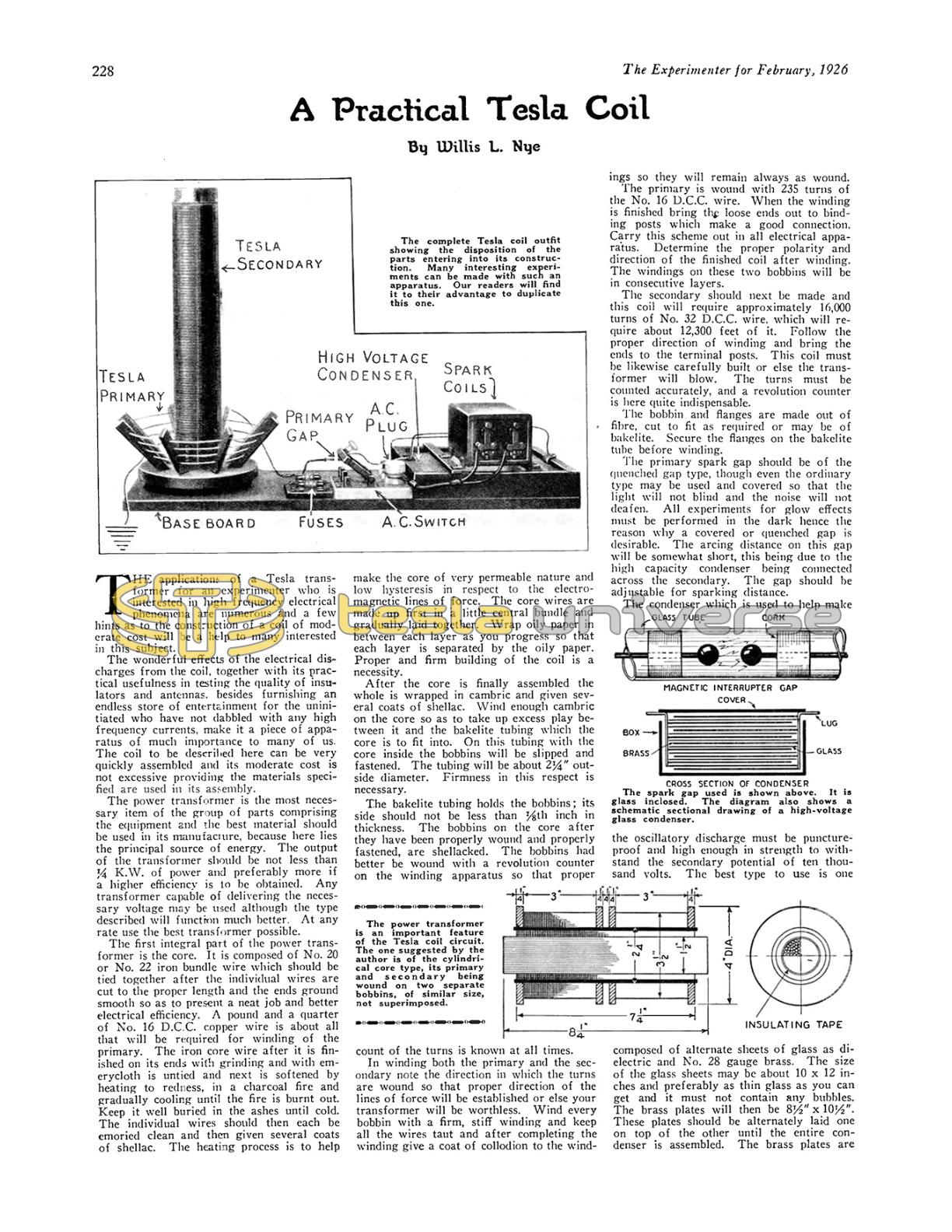
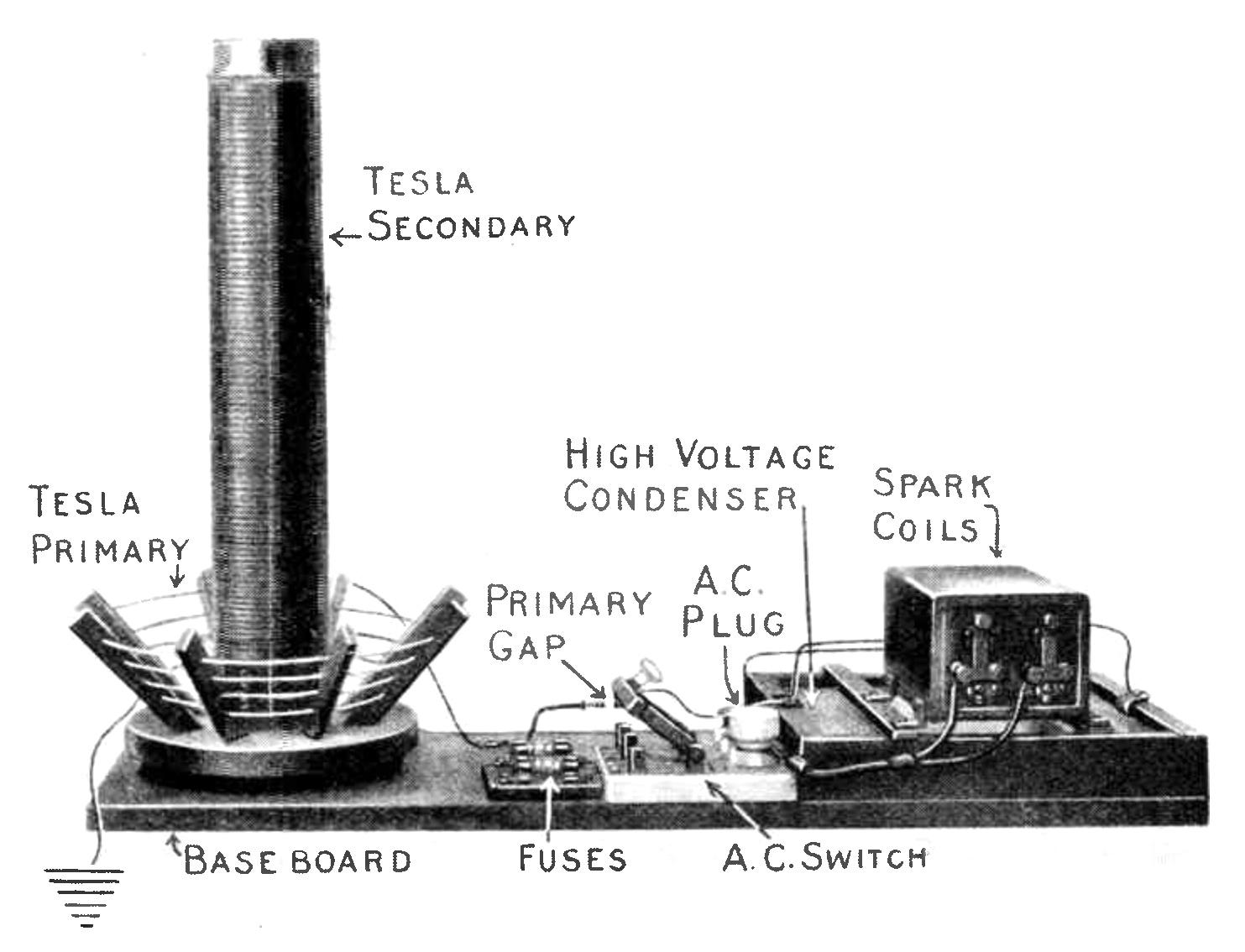
The wonderful effects of the electrical discharges from the coil, together with its practical usefulness in testing the quality of insulators and antennas, besides furnishing an endless store of entertainment for the uninitiated who have not dabbled with any high frequency currents, make it a piece of apparatus of much importance to many of us. The coil to be described here can be very quickly assembled and its moderate cost is not excessive providing the materials specified are used in its assembly.
The power transformer is the most necessary item of the group of parts comprising the equipment and the best material should be used in its manufacture, because here lies the principal source of energy. The output of the transformer should be not less than 1/4 K.W. of power and preferably more if a higher efficiency is to be obtained. Any transformer capable of delivering the necessary voltage may be used although the type described will function much better. At any rate use the best transformer possible.
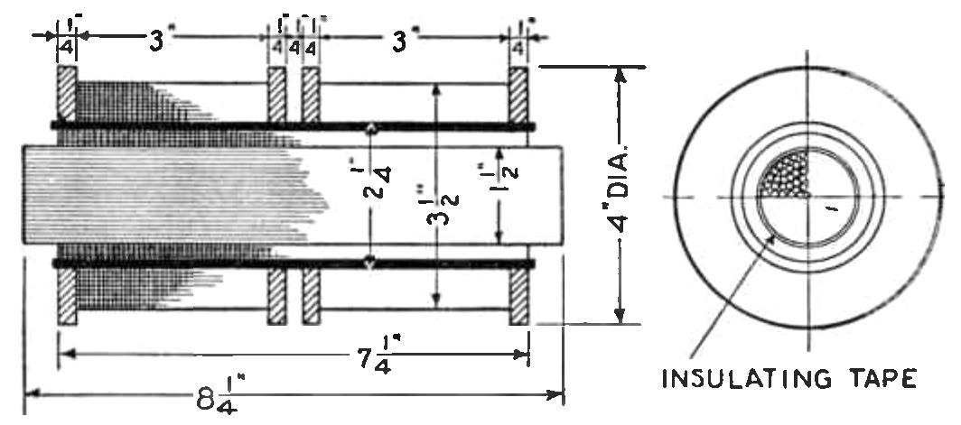
The first integral part of the power transformer is the core. It is composed of No. 20 or No. 22 iron bundle wire which should be tied together after the individual wires are cut to the proper length and the ends ground smooth so as to present a neat job and better electrical efficiency. A pound and a quarter of No. 16 D.C.C. copper wire is about all that will be required for winding of the primary. The iron core wire after it is finished on its ends with grinding and with emery cloth is untied and next is softened by heating to redness, in a charcoal fire and gradually cooling until the fire is burnt out. Keep it well buried in the ashes until cold. The individual wires should then each be emoried clean and then given several coats of shellac. The heating process is to help make the core of very permeable nature and low hysteresis in respect to the electro-magnetic lines of force. The core wires are made up first in a little central bundle and gradually laid together. Wrap oily paper in between each layer as you progress so that each layer is separated by the oily paper. Proper and firm building of the coil is a necessity.
After the core is finally assembled the whole is wrapped in cambric and given several coats of shellac. Wind enough cambric on the core so as to take up excess play between it and the bakelite tubing which the core is to fit into. On this tubing with the core inside the bobbins will be slipped and fastened. The tubing will be about 2 1/4" outside diameter. Firmness in this respect is necessary.
The bakelite tubing holds the bobbins; its side should not be less than 1/16th inch in thickness. The bobbins on the core after they have been properly wound and properly fastened, are shellacked. The bobbins had better be wound with a revolution counter on the winding apparatus so that proper count of the turns is known at all times.
In winding both the primary and the secondary note the direction in which the turns are wound so that proper direction of the lines of force will be established or else your transformer will be worthless. Wind every bobbin with a firm, stiff winding and keep all the wires taut and after completing the winding give a coat of collodion to the windings so they will remain always as wound.
The primary is wound with 235 turns of the No. 16 D.C.C. wire. When the winding is finished bring the loose ends out to binding posts which make a good connection. Carry this scheme out in all electrical apparatus. Determine the proper polarity and direction of the finished coil after winding. The windings on these two bobbins will be in consecutive layers.
The secondary should next be made and this coil will require approximately 16,000 turns of No. 32 D.C.C. wire, which will require about 12,300 feet of it. Follow the proper direction of winding and bring the ends to the terminal posts. This coil must be likewise carefully built or else the transformer will blow. The turns must be counted accurately, and a revolution counter is here quite indispensable.
The bobbin and flanges are made out of fibre, cut to fit as required or may be of bakelite. Secure the flanges on the bakelite tube before winding.
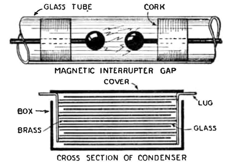
The primary spark gap should be of the quenched gap type, though even the ordinary type may be used and covered so that the light will not blind and the noise will not deafen. All experiments for glow effects must be performed in the dark hence the reason why a covered or quenched gap is desirable. The arcing distance on this gap will be somewhat short, this being due to the high capacity condenser being connected across the secondary. The gap should be adjustable for sparking distance.
The condenser which is used to help make the oscillatory discharge must be puncture-proof and high enough in strength to withstand the secondary potential of ten thousand volts. The best type to use is one composed of alternate sheets of glass as dielectric and No. 28 gauge brass. The size of the glass sheets may be about 10 x 12 inches and preferably as thin glass as you can get and it must not contain any bubbles. The brass plates will then be 8 1/2" x 10 1/2". These plates should be alternately laid one on top of the other until the entire condenser is assembled. The brass plates are alternately connected so as to form a condenser with the glass plates as dielectric.
Use an odd number of glass plates and an even number of brass plates. About 25 plates of glass and 24 plates of brass give a very high capacity, and will give good results. A lower capacity may be used but the discharges will be less powerful. The condenser brass plates should all be cut so they have a lug on each and then the lugs are brought out to terminal posts. Place this condenser in a redwood box and wedge all in securely so the plates will not become displaced. This condenser when it is charged will give a bad shock if the body comes in contact with its electrodes.
The first transformer ratio you will note is 1 to 100. The same applies to the input to the Tesla transformer. Maintain this voltage ratio on any coil you may make in this line.
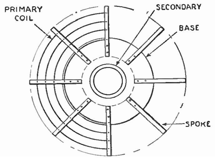
The primary coil of the Tesla transformer is now to be built and it is well to build it on the lattice work skeleton as shown in the diagram. However, bakelite tubing may be used in this particular part. From the results which have been obtained, it is perhaps best to use the wood framework. Make the coil truncated cone shaped inverted toward the base of the transformer. All wood used in any of this construction should be shellacked and of the redwood variety. The pieces should be all held together with pegs or dowels of wood and the wire is passed through the holes in each rib to secure the ends. No metallic object should be used in the coil or frame or else the coil will energize them and a brush discharge will occur. The base carrying the ribs that hold the primary should be 10 inches in diameter. Assemble all very firmly. Tinned copper wire with 7 strand No. 22 gauge wire may be used for the primary winding.
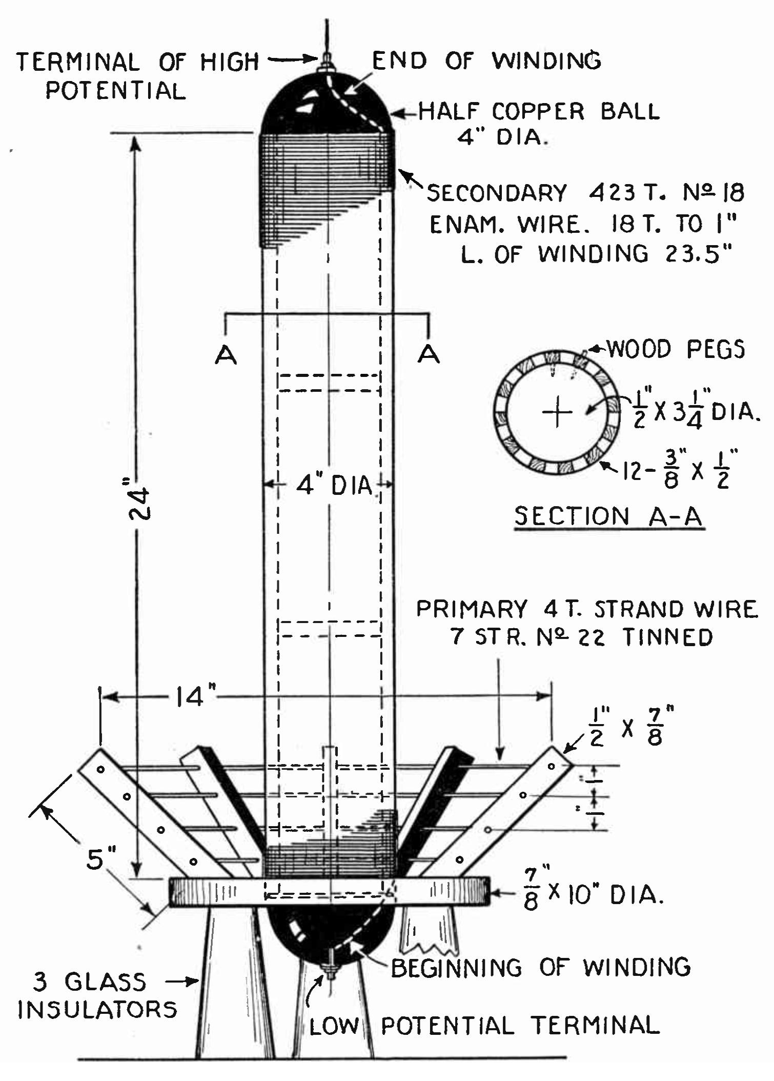
The secondary is carried by the wooden frame; bakelite or hard rubber tubing can be used. Make the frame of the dimension shown. Keep to these dimensions or reduce or increase in the same ratio. The tall sticks of the lattice work are likewise fastened with wooden pegs; four circular formers are necessary, the ones at the lower end should be made so that the secondary can be detached for portability. Electrical contacts are made at the bottom. The half balls of sheet copper on the ends of the secondary help the charge to accumulate and become dense. They are obtained at a metal spinner's shop and cost but little. See that the balls fit snugly on the ends. Make a binding post at the center extremity of each ball. Begin the winding on the secondary at the bottom and start winding toward the top. No. 18 to No. 22 enameled wire is used here. Wind very taut and determine proper direction in regards to primary and then solder the ends to the tips of the two copper balls. Keep the surfaces of the copper balls highly polished. When all assembly work is done wire up the Tesla coil unit itself.
Mount all the apparatus on a base of wood 3 feet long and 18 inches wide and shellacked thoroughly. In wiring allow sufficient clearance between all the apparatus. The whole group of apparatus can be set on top of long-necked jelly glasses, which are fine insulators. Be sure to keep the high frequency current from leakage to the ground or else the actual output at the top of the Tesla secondary will be small.
After final assembly the wiring to the house-line current should be made and the proper switches and fuses inserted in the line. A liberal use of fuses will prevent kick-backs through the house system.
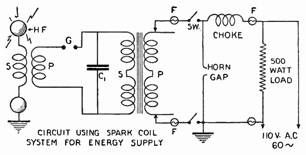
A lower-powered coil may be made by substituting the supply of a parallel set of 1/4 K.W. spark coils, in place of the large power transformer. This will give about 50 per cent. of the discharge obtainable with the large transformer. You may connect the spark coils on the A.C. 110-volt line, using a 500-watt flat-iron in parallel with them so the A.C. will not puncture their insulation. These two spark coils are the usual automobile ignition coils.
This improvised coil stunt is fine business for low power and it is well for one who wants to build one of the larger coils permanently to make one of the low power and determine the best positions, spacing, etc., of the apparatus. By this method one is enabled to incorporate all the experience into the larger coil when it is finally built. It is best for all who construct Tesla coils to experiment a bit with different makes of primaries and condensers, so as to obtain the best results. It is an individual problem to solve.
If any deviations are made from given dimensions, turns and size of wire, etc., it is well to carry out the same proportions, because these have only been determined after many types were tried and discarded in their favor. Insulate all parts carrying current thoroughly and wire all with a very stiff bus-bar wire so that there can be no short circuits.
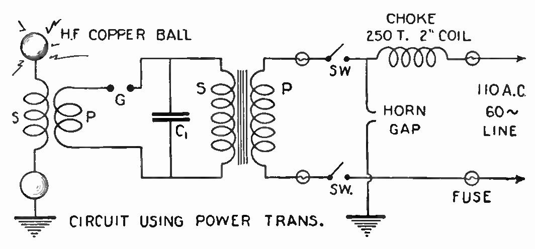
The general layout and hook-up are given both for the transformer input and the spark-coil supply. Note carefully the fusing as employed, because some time a "kick-back" on the line may blow all the fuses on the house line. The choke should be wound on a 2" coil form and contain 250 turns No. 24 D.C.C. wire. The horn gap should be connected as shown and will aid in grounding any back line surge from the transformer. Note particularly all connections shown and determine which carry low frequency current from the high frequency lines and be very cautious when handling these as they may give a very severe shock.
Many wonderful experiments may be performed with this coil with the Geissler tube and wonderful glows in a dark room will result. An ordinary incandescent globe will produce a beautiful lavender glow.
A wire may be connected to the high potential end of the coil and a great brush discharge will take place, making a dull glow and crackling sound. The wire should be cut and lengthened until the proper length is found, at which the greatest discharge will occur and produce the most brilliant glow.
The insulating qualities of this coil if they are good will help prevent excess brush discharges and only in this way can the fullest results be obtained. To test the insulating qualities of slate, marble, bakelite, celeron is a very interesting process and one will be surprised at the results. Many preconceived "notions" will be "blasted" after these tests are made.
Another interesting experiment is to make a long wire spinner, place it on a needle-bearing at the tip of the coil and watch it revolve at a high rate of speed depending on the frequency of the current. This gives a good photograph.
The same result showing whether one is getting complete "CW" from his transmitter is to place the Tesla secondary inside the "CW" inductance and apply the power supply. This is a "modulatoscope." Accurate results will require photographing the discharge. With these conclusions one may place the necessary chokes and filters in his plate supply line to produce the best wave.
The breakdown qualities of a condenser of mica, glass or other dielectric can be readily found out by connecting it to the high potential. Perhaps the most peculiar experiment is to test the insulation of a so-called safety screw-driver used by electricians. Note the results.
The discharges may be taken by the person performing these experiments employing a metallic rod to draw them off. This is not a painful practice. In fact, the actual discharge on to one's finger tips is rather exhilarating. These high frequency currents travel on the outside of the body and cause no apparent harm. This cannot be said of the low frequency current. Play safe!
The antenna for radio purposes may readily be tested for insulation leakage by applying the high potential and searching for it with a neon gas spark plug tester which glows when a high frequency current passes through it.
Do all antenna testing at a time of the day when the radio listeners are not receiving the broadcasts or else you'll "QRM" the whole neighborhood. This need hardly be said to a real true experimenter, but it is a precaution. Conduct all these experiments as quickly as possible if in the evening, because the discharges will interfere with radio reception.
With this Tesla transformer one may conduct an endless number of experiments which are too numerous to mention here and it will be well to look up some information on high frequency currents before actually doing any experiments or else one may not know the meaning of it all.
This simple apparatus should prove a delight to one's friends who are interested in experimental work and if several persons become engaged in the research some very fine results will be deduced. The field of high frequency currents is a broad one and to the "radio fiend" they will be a boon because they will enable him to more clearly visualize the actual mediums in existence, as we may express it, and thus enable one to become more thoroughly familiar with the "greatest indoor sport" of the time.
While the transformer is in actual conversion of the low potential to high potential it is well to be extremely cautious in all the adjusting because the low frequency current with such a high voltage stored up in the condenser is liable to cause injury if you happen to receive an electrical shock. Constant caution will well repay and is to be preferred to saying it with flowers.