Plans
Spectacular High Frequency Experiments
Made with Aid of Junked Ignition Coil
By KENDALL FORD
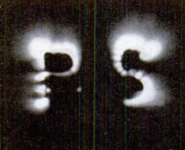
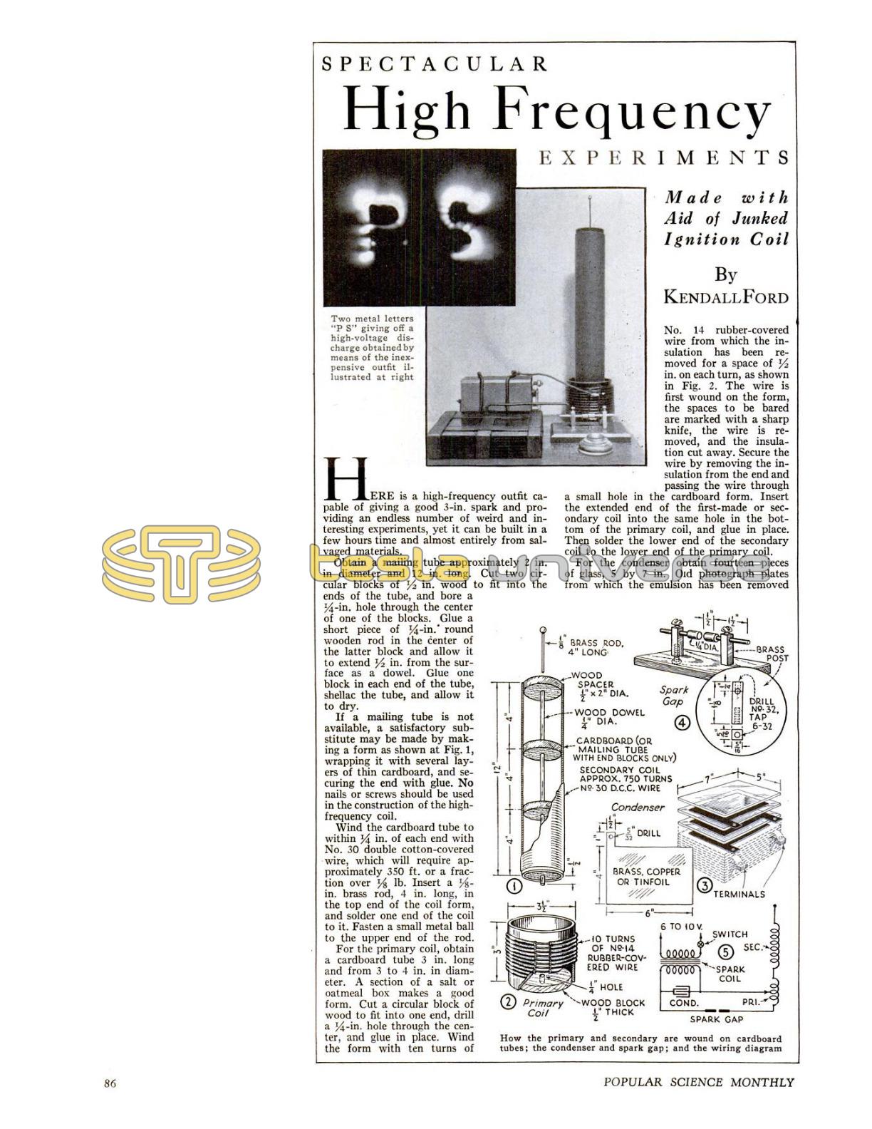
Here is a high-frequency outfit capable of giving a good 3-in. spark and providing an endless number of weird and interesting experiments, yet it can be built in a few hours time and almost entirely from salvaged materials.
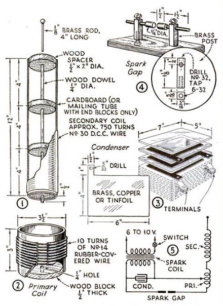
Obtain a mailing tube approximately 2 in. in diameter and 12 in. long. Cut two circular blocks of 1/2 in. wood to fit into the ends of the tube, and bore a 1/4-in. hole through the center of one of the blocks. Glue a short piece of 1/4-in. round wooden rod in the center of the latter block and allow it to extend 1/2 in. from the surface as a dowel. Glue one block in each end of the tube, shellac the tube, and allow it to dry.
If a mailing tube is not available, a satisfactory substitute may be made by making a form as shown at Fig. 1, wrapping it with several layers of thin cardboard, and securing the end with glue. No nails or screws should be used in the construction of the high-frequency coil.
Wind the cardboard tube to within 1/4 in. of each end with No. 30 double cotton-covered wire, which will require approximately 350 ft. or a fraction over 1/8 lb. Insert a 1/8-in. brass rod, 4 in. long, in the top end of the coil form, and solder one end of the coil to it. Fasten a small metal ball to the upper end of the rod.
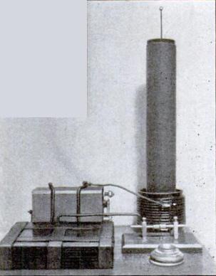
For the primary coil, obtain a cardboard tube 3 in. long and from 3 to 4 in. in diameter. A section of a salt or oatmeal box makes a good form. Cut a circular block of wood to fit into one end, drill a 1/4-in. hole through the center, and glue in place. Wind the form with ten turns of No. 14 rubber-covered wire from which the insulation has been removed for a space of 1/2 in. on each turn, as shown in Fig. 2. The wire is first wound on the form, the spaces to be bared are marked with a sharp knife, the wire is removed, and the insulation cut away. Secure the wire by removing the insulation from the end and passing the wire through a small hole in the cardboard form. Insert the extended end of the first-made or secondary coil into the same hole in the bottom of the primary coil, and glue in place. Then solder the lower end of the secondary coil to the lower end of the primary coil.
A Low-Cost Outfit
Expense need no longer stop you from building your own high-frequency apparatus. Mr. Ford, who is a master at making fine electrical equipment from odds and ends, has designed this outfit so that it can be made at trifling cost. His plans are offered in response to the great interest shown by readers in our recent article on a much larger Tesla coil (P. S. M., Dec. '34, p. 65), which required a high-voltage transformer.
For the condenser obtain fourteen pieces of glass, 5 by 7 in. Old photograph plates from which the emulsion has been removed are excellent, but any scrap pieces of glass will do. Cut thirteen pieces of brass, copper, or tinfoil to the size and shape shown in Fig. 3. Drill holes in the tabs at the end of the sheet for connecting screws as shown. In stacking the condenser, place a sheet of glass on a flat surface, then a sheet of foil on the glass, another sheet of glass, then a sheet of foil with the tab at the opposite end. Continue until the condenser is assembled as in Fig. 3. The foil should be placed on the glass so that there is a margin of 1/2 in. all the way around. Bind the condenser together with friction tape.
The details of the spark gap are shown in Fig. 4. Two brass posts are mounted on a block of well-seasoned wood, and the adjustable electrodes made from pieces of 1/4-in. round brass rod soldered to 1/8-in. pieces. The latter are held by means of No. 6-32 set screws.
A vibrator type Ford ignition coil will be required to excite the high-frequency coil. One may be obtained from any auto wrecking yard, but make certain that the condenser within the coil is not damaged. If the coil gives a hot spark at least 1/2 in. long, it will be satisfactory.
The diagram of connections is shown in Fig. 5. The wire from the spark coil to the primary of the high-frequency coil should be flexible and should terminate in a spring clip to enable its being connected at any turn of the primary coil. The spark gap should be separated not more than 1/16 in. Connect the primary to a transformer or battery of from 6 to 10 volts, and vary the number of primary turns in the circuit until the longest spark is obtained from the discharge ball at the top of the coil. If the coil is operated in semidarkness, the effects are most spectacular, due to the fine corona discharge that surrounds the upper coil but is not visible in a strong light.