Nikola Tesla Articles
Alternating Current Motors: The Evolution of a New Type
On giving our secretary the title of this paper it was my purpose to treat the subject in a broader light, and to show the progressive steps in a series of experiments which led eventually to the type of machine that I shall bring to your notice this evening. The recent and urgent claims of other work have rendered such a treatment impossible at the present, and I shall limit the paper to a description of a new alternating-current motor, one form of which is shown in the accompanying drawings.
The place that the alternating-current electric motor is destined to fill in the industrial arts is familiar to you all, and the various ways known to the scientific world by which such machines may be rendered operative have been ably considered and elaborately discussed in the institute papers of the past two years by Prof. Thomson, Dr. Duncan, and Mr. Tesla. We are thus all more or less acquainted with the prominent difficulties of the problem.
My experience in common with that of my predecessors teaches that the alternating-current motor has a strong and persistent disposition to stand still, and when persuaded to motion it is apt to be a sort of "go as you please" machine and asserts its inherent right to turn in either direction indifferently, direction of rotation in some cases being purely a matter of chance. I shall not have much to say about efficiency, as my experiments with large machines are not sufficiently advanced to furnish any reliable data, but I will endeavour to give a general solution of the problem designed to meet the following conditions of practice:
1. A machine that will start itself independently of the speed of the generator or number of alternations of current per unit of time.
2. A machine that has but one direction of rotation and cannot reverse under any conditions of current alternation.
3. A machine that is not necessarily synchronous with the generator, revolution for revolution.
4. A machine in which reversals of current direction do not produce corresponding reversals of magnetism in any iron part when the machine is in motion at its normal speed and maximum efficiency.
5. A machine of simple form, having an ordinary continuous wound armature revolving in a single or two-pole field.
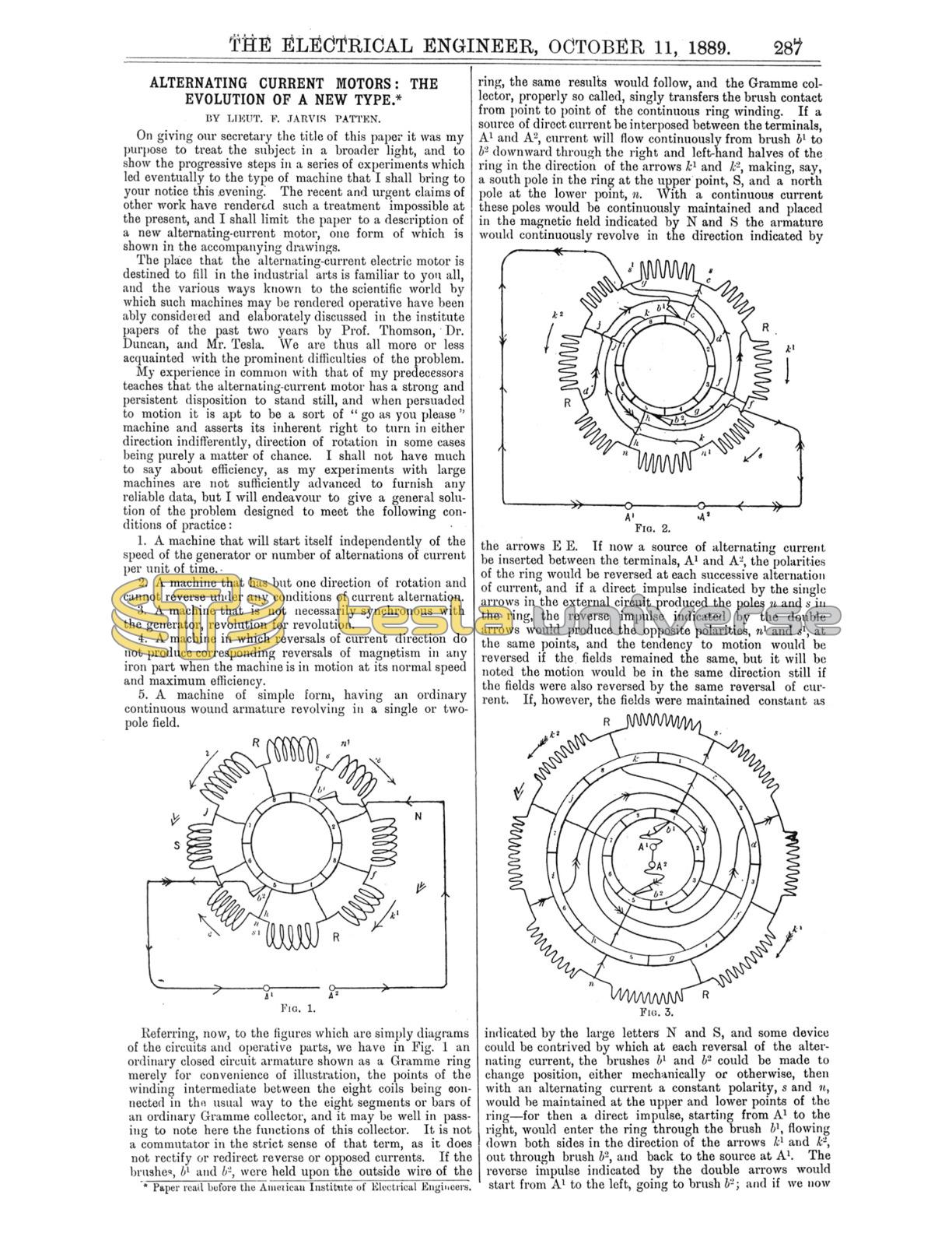
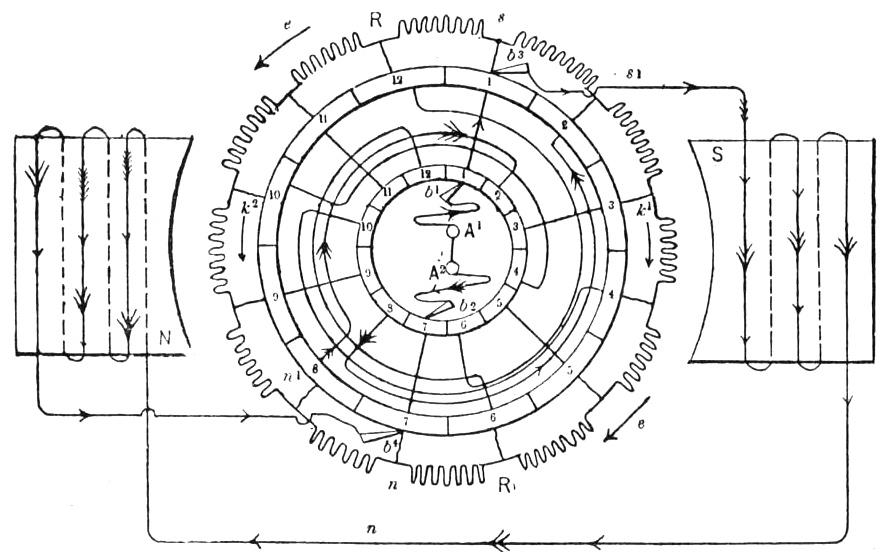
Referring, now, to the figures which are simply diagrams of the circuits and operative parts, we have in Fig. 1 an ordinary closed circuit armature shown as a Gramme ring merely for convenience of illustration, the points of the winding intermediate between the eight coils being connected in the usual way to the eight segments or bars of an ordinary Gramme collector, and it may be well in passing to note here the functions of this collector. It is not a commutator in the strict sense of that term, as it does not rectify or redirect reverse or opposed currents. If the brushes, b1 and b2, were held upon the outside wire of the ring, the same results would follow, and the Gramme collector, properly so called, singly transfers the brush contact from point to point of the continuous ring winding. If a source of direct current be interposed between the terminals, A1 and A2, current will flow continuously from brush b1 to b2 downward through the right and left-hand halves of the ring in the direction of the arrows k1 and k2, making, say, a south pole in the ring at the upper point, S, and a north pole at the lower point, n. With a continuous current these poles would be continuously maintained and placed in the magnetic field indicated by N and S the armature would continuously revolve in the direction indicated by the arrows E E. If now a source of alternating current be inserted between the terminals, A1 and A2, the polarities of the ring would be reversed at each successive alternation of current, and if a direct impulse indicated by the single arrows in the external circuit produced the poles n and s in the ring, the reverse impulse indicated by the double arrows would produce the opposite polarities, n1 and s1, at the same points, and the tendency to motion would be reversed if the fields remained the same, but it will be noted the motion would be in the same direction still if the fields were also reversed by the same reversal of current. If, however, the fields were maintained constant as indicated by the large letters N and S, and some device could be contrived by which at each reversal of the alternating current, the brushes b1 and b2 could be made to change position, either mechanically or otherwise, then with an alternating current a constant polarity, s and n, would be maintained at the upper and lower points of the ring - for then a direct impulse, starting from A1 to the right, would enter the ring through the brush b1, flowing down both sides in the direction of the arrows k1 and k2, out through brush b2, and back to the source at A1. The reverse impulse indicated by the double arrows would start from A1 to the left, going to brush b2; and if we now suppose this to have changed places with the brush b1, the reverse current would then enter the ring at s, and flowing down both sides in the direction of the arrows k1 and k2, would leave through n and the brush b1 and so back to the source a2, maintaining the polarity of the ring the same as before. If the brushes could be thus changed at each alternation, the polarity of the ring would be maintained constant with an alternating current. While, however, it is quite impracticable to thus cause the brushes to change position mechanically at each reversal of current, it is perfectly feasible to produce the same effect without the mechanical change.
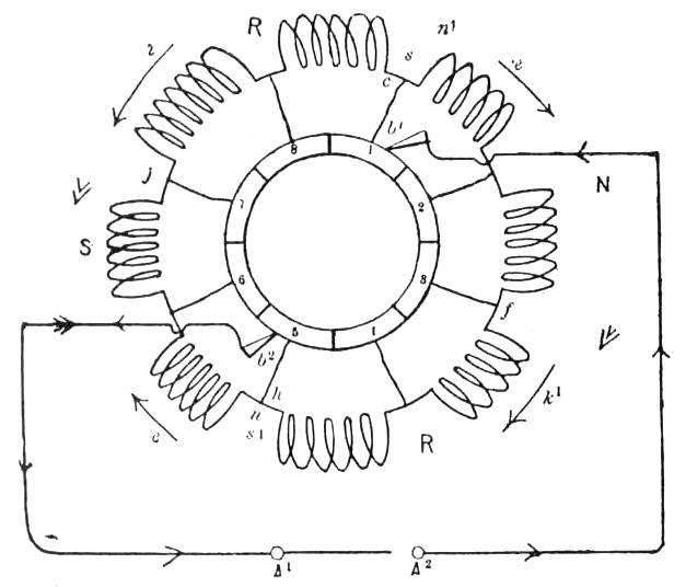
The means of accomplishing this result are indicated in Fig. 2, which is identical with Fig 1, with a single exception. There are eight coils, as before, and eight bars in the collector; the odd numbered bars, 1, 3, 5, and 7, are connected to the same points of the ring as before c, f, h, and j, but the even numbered bars, 2, 4, 6, 8, are connected respectively to points of the ring diametrically opposite them, bar 2 to the point d, bar 4 to tho point g, and so on, each even numbered bar to a correspondingly opposite point of the winding. If now a source of alternating current be interposed between the terminals, A1 and A2, and we make the single supposition that the ring shall turn through an arc of the circumference equal to that covered by one bar of the collector during each alternation of current, we shall still maintain a constant polarity at the upper and lower points of the ring without causing the brushes to change position mechanically.
Thus a positive impulse starting from A1 to the left and indicated by single arrows enters the ring at b1, flows down both sides to n, producing the ring polarities s and n, out brush b2 and back to source at A2. The reverse impulse being in the opposite direction will start from A2 to the right, go to brush b2, which we will now suppose bearing on segment 4 of the collector, whence it will go by the inverse connection to the opposite point, B1, of the ring, then down both sides in the same direction as before to the point n1, thence back to the opposite segment 8, out brush b1, now bearing on this segment, and back to source at A1.
The reverse currents, therefore, under the assumed conditions are caused to maintain a constant polarity in the ring, so that in a constant field its tendency to motion would always be in the same direction with an alternating current in the armature. It will be further noted that the alternating current is not redirected or commuted in the strict sense of the word, and we may enunciate the fundamental principle which underlies the construction of this type of machine as follows:
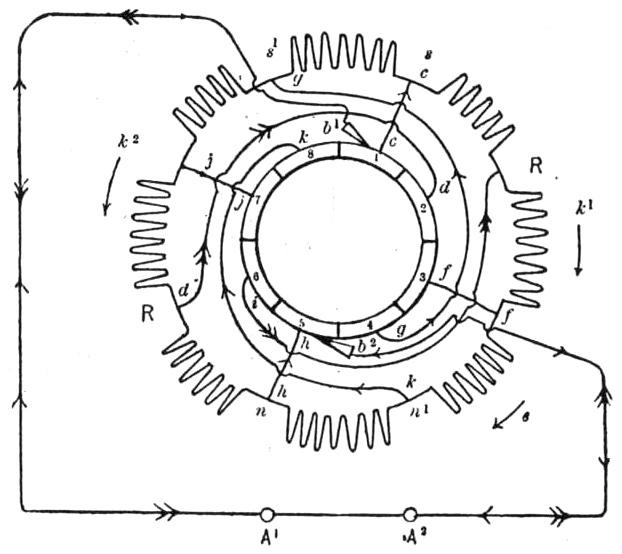
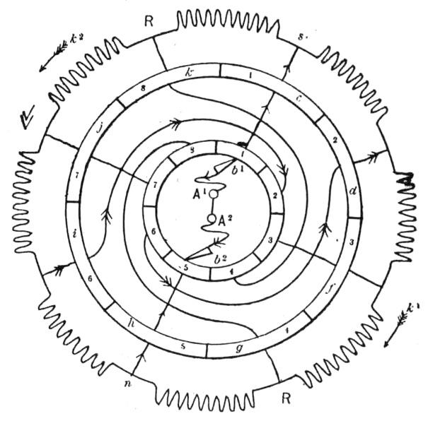
The poles of any closed circuit may be maintained constant with an alternating current by causing opposite impulses to traverse the circuit in opposite directions. The direct and inverse connections, shown in Fig. 2, have precisely this effect, when, as supposed, a single bar of the collector passes under the brushes at each reversal of currrent. The connections c c, d d, f f, etc. in Fig. 2 may have any form, and other bars may be interposed between their extremities without affecting in any way their functions as connectors. This step is shown, in Fig. 3, where another collector bar, 1c 2d, 3f, etc., is inserted in each of the connections c c, d d, etc., of Fig. 3, thus making another collector shown outside the first to avoid confusion of the drawing, while, for the same reason, the source of alternating current, A1 A2, is placed inside the inner ring. As the polarities, s and n, of the ring are maintained constant, as previously described, with an alternating current, and current is constant in direction from s downward through the right and left halves of the rings to n, so must necessarily any current be constant in direction which is led from brushes through any shunt circuit connected to the segments, 1c and 5h, of the outer collector; a field circuit of constant direction may therefore be shunted from this outside collector. This is shown in Fig. 4, in which 12 coils are shown in the ring, and 12 bars in each collector connected alternately direct and inverse, as before. Tracing now two opposite impulses of current, we have the first indicated by the single arrows from source A1 to segment 1 of the inner collector, thence to segment 1 of outer collector, where the current divides, part going down the right and left-hand halves of the ring to n, and part out brush b3 through the field circuit, making the poles N and S back to brush b1, segment 7, of outer, and segment 7 of inner collector to the terminal A2 of source. If the armature be supposed now to turn through the space covered by one collector bar, the reverse impulse can be traced as follows: Starting at A2 in the opposite direction to brush b2, now bearing on segment 8 of the inner collector, thence through the reverse connection to segment 2 of the outer collector, now under brush b3, where the current divides, going part as before down the right and left halves of the ring, making a south pole at s1 and a north pole at n1 as before, and the other part out of brush b3, through the field circuit in the same direction as before, back to brush b4, now on segment 8 of the outer ring, thence through the reverse connection back to segment 2 of the inner ring, now in bearing with brush b1, and so returning to the source at A1. Thus the two impulses of opposite direction have been made to traverse both armature and field circuits in the same direction. We have, therefore, with an alternating current constant armature polarity and constant field polarity, and therefore a constant tendency to motion in the same direction. Not only this, but the further condition is fulfilled that there are no reversals of magnetism in any iron part so long as one bar in the machine, as shown in Fig. 4, passes under the brushes at each alternation of current. It remains to show how this is brought about. Referring again to Fig. 4, let it be supposed that the first impulse of current did not cause the armature to turn through the arc of the circumference subtended by one segment, but all the branches still bore on the same segments as shown in the figure and the reversals of current continued. By tracing the circuits it will be seen that each reversal of current reverses the polarity of both field and armature, and with either direction of current or rapid reversals there will be a constant tendency to motion always exerted in the same direction. The machine under these conditions becomes therefore simply a direct-current machine on an alternating-current circuit, with a constant tendency to start in one direction. Assuming the machine therefore self-starting, it will continually gain in speed until the condition is fulfilled of one segment passing the brushes at each alternation, for it then becomes in the broad sense a synchronous alternating motor, the current then produces no reversals of magnetism, and there is a true alternating current in the armature circuit, producing, however, no reversal of armature polarity; and a current of constant direction in the field. Under these conditions the motor is self-regulating, moving at a constant speed and with a maximum rotary effort.
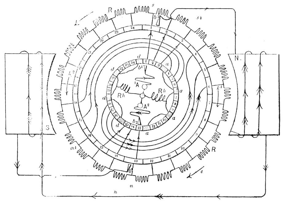
It is not, however, essential that one bar should pass the brush at each alternation, as any number may be caused to do this depending upon the speed required and the number of coils upon the armature. This is illustrated in Fig. 5, where the complete machine is shown. There are 24 coils in the armature, 24 bars in the outside collector, and 32 bars in the inside one, this latter being composed of 24 connecting and eight insulating bars. The connecting bars of the inner ring are numbered to correspond with those of the outer ring around to the right from one to 24 - the insulating bars, drawn shaded, separate the others into groups of three. In this machine three segments 1, 2, 3, in the outer ring are connected direct to the corresponding segments 1, 2, 3 of the inner ring, likewise the opposite three, 13,14,15, of one ring are connected direct to 13, 14, 15 of the other. The next group of three is connected inversely, 4, 5, 6 of the outer ring to the diametrically opposite bars 16, 17 and 18 of the inner ring, and the corresponding opposite group, 16, 17, 18, of the outer ring is likewise connected inversely to the diametrically opposite group 4, 5 and 6, of the inner ring. The remaining segments are connected in the same manner, but the connections are omitted to avoid confusion in the drawing. The operation of the machine is evidently the same as that shown in Fig. 4, except that the required conditions are fulfilled in this instance when three bars of the collector pass under the ring at each alternation of current, and as there are 24 segments, arranged in groups of three, the machine at its normal speed would make one revolution for every eight alternations of current, and connected in a circuit supplied with 16,000 reversals per minute its normal speed would be 16,000/8 = 2,000 per minute, and with 48 segments arranged in groups of three, its speed would be 1,000 per minute. The blank segments insulating the groups of the inner ring are connected to the extremities of a rheostat, Rh. Rh., which is enclosed inside the commutator, and is designed to offer a path for the alternating current such as there may be, and prevent its absolute rupture at the period of change from one group of segments to the next; they also serve an important purpose in preventing a dangerous short circuit, which would be occasioned by the inner brush bridging two groups of segments oppositely connected.
It follows, as a matter of course, that as the machine starts as a direct-current motor connected in an alternating circuit, rapid reversals of magnetism will at first be produced in all the iron cores, and these should be made of laminated iron to prevent undue loss by heating at the period of starting. The machine, in fact, starts as a direct-current motor, and automatically changes to a sort of synchronously alternating motor. When it gains its normal speed at this point it is self-regulating, and its capacity of doing work is a maximum.
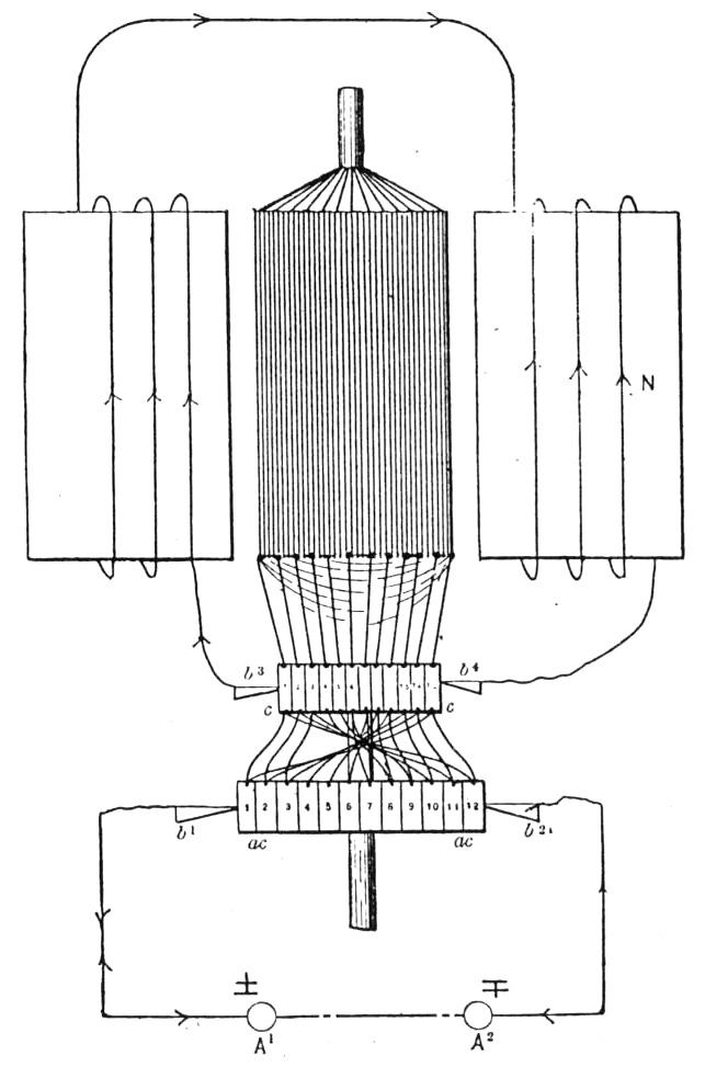
Fig. 6 shows a plan of the machine as constructed; it consists simply of an ordinary closed circuit armature in a single field; c, c is the ordinary collector, really a part of the armature circuit, from which the brushes, b3, b4, take a current of constant direction to the field-shunt; a c, a c is the reversely connected commutator and the brushes, b1, b2, bearing upon this commutator are connected to the terminals of the alternating-current circuit.
* Paper read before the American Institute of Electrical Engineers.