Nikola Tesla Articles
Ewing's High Frequency Alternator
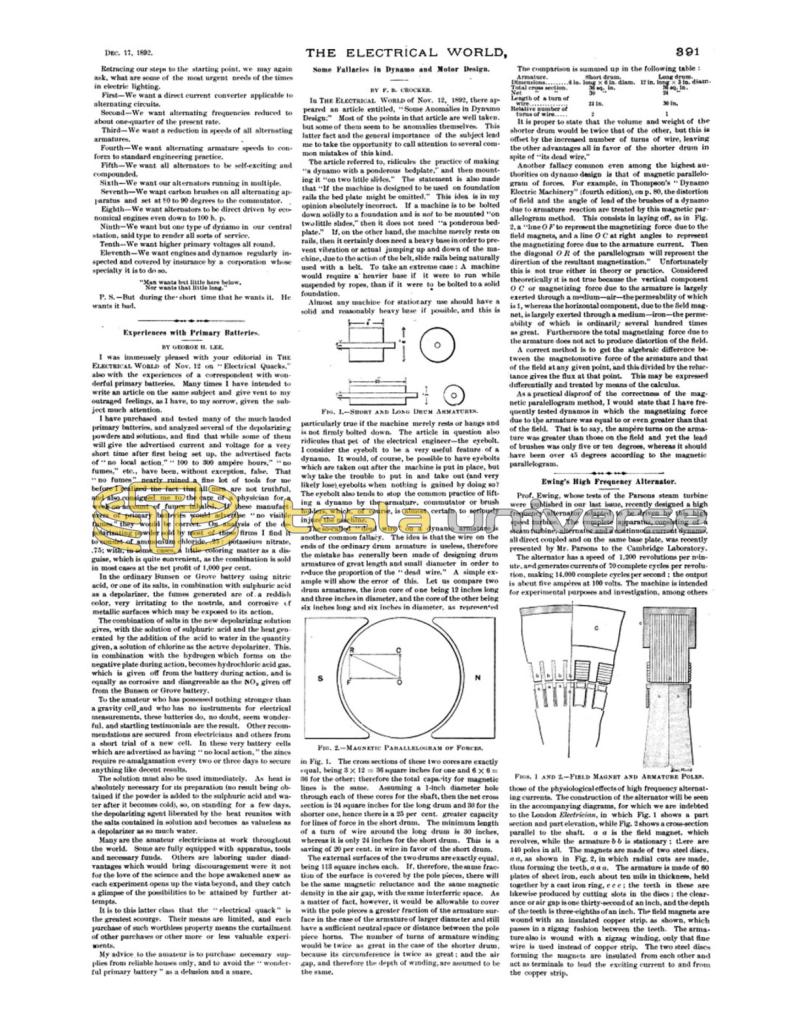
Prof. Ewing, whose tests of the Parsons steam turbine were published in our last issue, recently designed a high frequency alternator adapted to be driven by this high speed turbine. The complete apparatus, consisting of a steam turbine, alternator and a continuous current dynamo, all direct coupled and on the same base plate, was recently presented by Mr. Parsons to the Cambridge Laboratory.
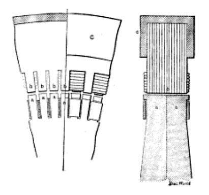
The alternator has a speed of 1,200 revolutions per minute, and generates currents of 70 complete cycles per revolution, making 14,000 complete cycles per second; the output is about five amperes at 100 volts. The machine is intended for experimental purposes and investigation, among others those of the physiological effects of high frequency alternating currents. The construction of the alternator will be seen in the accompanying diagrams, for which we are indebted to the London Electrician, in which Fig. 1 shows a part section and part elevation, while Fig. 2 shows a cross-section parallel to the shaft. a a is the field magnet, which revolves, while the armature b b is stationary; there are 140 poles in all. The magnets are made of two steel discs, a a, as shown in Fig. 2, in which radial cuts are made, thus forming the teeth, a a a. The armature is made of 60 plates of sheet iron, each about ten mils in thickness, held together by a cast iron ring, c c c; the teeth in these are likewise produced by cutting slots in the discs; the clearance or air gap is one thirty-second of an inch, and the depth of the teeth is three-eighths of an inch. The field magnets are wound with an insulated copper strip, as shown, which passes in a zigzag fashion between the teeth. The armature also is wound with a zigzag winding, only that fine wire is used instead of copper strip. The two steel discs forming the magnets are insulated from each other and act as terminals to lead the exciting current to and from the copper strip.

