
Nikola Tesla Articles
Inside Project Tesla
The quest to create lightning most likely originated with our pre-historic ancestors when they observed it setting trees on fire. Much later, it continued when some fool went out in the rain with a kite (Ben Franklin). Earlier this century, the first glimmerings of success was obtained by Nikola Tesla during his spectacular Colorado Springs experiments. Today, the art has been rekindled and is slowly being refined in a remote mountainous location near Leadville, Colorado.
This arduous attempt to harness the forces of nature has been appropriately titled "Project Tesla" and has come about because of the persistence of Robert Golka - creator and manager of Project Tesla.
The centerpiece of Project Tesla is a near replica of Tesla's Magnifying Transmitter which he built in Colorado Springs. A stunning 51 feet diameter primary/secondary coil combination rises from the floor dwarfing the rest of the equipment - industrial sized transformers, capacitors and spark gaps. Naturally, any Tesla coil needs a wall socket to plug into somewhere. Big as this one is, it is no exception to the rule and is powered by a nearby generator. Additional features to this coil includes a free-standing two story extra coil and a 260 foot elevated capacitance.
Although building a Goliath Tesla coil is beyond the means of most people, research with such a device may help us understand lightning and lightning-like effects. Additional benefits may be reaped in the areas of plasma control and ultimately - it is hoped - wireless power transmission.
Historical Background
Project Tesla had its origins in ball lightning research. In 1968 one very persistent researcher - Robert Golka - began his attempts to study ball lightning. His early failures to achieve ball lightning through the use of Oudin coils led him to the writings of Nikola Tesla which he discovered during a 1969 trip to Yugoslavia. Inspired by Tesla's Colorado Springs experiments, Mr. Golka spent the next three years fund raising and accumulating equipment.
In May of 1973, Project Tesla was set up on the Bonneville Salt Flats for the dual purposes of ball lightning generation and to do ground conductivity studies for the US Navy. Instead of easy success, Robert was greeted with some harsh news - his knowledge of coils was totally inadequate for the task he had undertaken. Due to major differences in the operation of giant and small Tesla coils, he had spend the summer to learning how to operate a giant coils.
Nature was determined not to be very co-operative in this quest to unlock her secrets and responded by flooding the project site later in the summer. Faced with this additional impediment, Golka spent the fall and winter in Stateline, Nevada where he was able to lease the Enola Gay's hangar for a nominal fee. Needless to say, the Project was moved immediately.
Finally, on July 4, 1974, the coil began operating properly. While at Wendover Air Force Base, Golka's Tesla coil (more properly a magnifying transmitter) was used to do lightning attachment studies on aircraft for the US Air Force. The high frequency nature of the Tesla coil generates a number of long arcs with random lengths and paths. This randomness reduces test bias inherent in methods using Marx Generators.
After a lengthy respite, Project Tesla was revived for replication of Tesla's research into wireless power transmission. Hoping that a thinner atmosphere increase the duration that the elevated capacitance would hold a charge, Leadville, Colorado was picked for the target site. The low atmospheric pressure was expected to have other side effects such as longer sparks.

Coil Overview
An overly simplified description of the Magnifying Transmitter would be to call it "a souped up Tesla coil." A Tesla coil has only five basic components:
- a conventional transformer,
- a capacitor (or condenser),
- a spark gap,
- a primary coil,
- a secondary coil (may have a terminal).
The Magnifying Transmitter has a sixth component common known as the "extra coil."
A tabletop Tesla coil operates in a very simple manner. The transformer takes a low voltage AC or pulsed DC power source and steps the voltage up to about 12,000 volts. The high-voltage capacitor is charged up to a potential large enough to breakdown the air resistance across the spark gap. This breakdown then allows the energy accumulated in the capacitor to burst through the primary coil and induce a current in the secondary. The frequency of this series of events is determined to a large extent by the setting of the spark gap. The larger the air gap, the lower the frequency of operation.


The secondary in a Tesla coil favors a particular rate of oscillation. If pulsated with electrical pulses at that preferred rate, the output will be forced to extremely high values. The coil will be in what is known as "resonance." It is from this feature that the Tesla coil and its derivative - the Magnifying Transmitter - draw their power. Resonance and its numerous applications is the basis of many of Tesla's inventions.
Now take this simple coil, enlarge it and attach a third (or extra) coil, which is tuned to the same resonant frequency, in series with the secondary. (Tesla first did this on July 7, 1899!) With this simple step, the simple Tesla coil is converted into a magnifying transmitter. The extra coil is an application of the quarter-wave principle and works best when it is attached to the secondary. It can, however, generate high voltages in the unattached or "stand alone" mode when in the vicinity of an operating Tesla coil.

One can easily note that the only major difference between the average Tesla Coil and the Tesla Magnifying Transmitter is the extra coil.
Transformer
Tesla used the Colorado Spring Municipal Power Plant for his power - which was supplied free of charge. In his specially built 110 square feet lab, a 50,000 volt Westinghouse transformer supplied the power necessary for his Magnifying Transmitter. An unfortunate incident in which Tesla burnt out one of the city's generators ultimately resulted in Tesla having access only to the generator which he - and his assistants - repaired and installed protective devices to prevent future recurrences.
In contrast, Golka's latest coil is powered by a 16 cylinder 790KW Detroit Diesel generator similar to those found in large scale mining operations. This particular unit, its fuel tank and main controls were self-contained in a semi-trailer. For control during operation of the coil, a remote control unit for it has been devised. Such a setup allows for portability of equipment and provides a more amenable environment than would otherwise be expected at 10,000 feet or more.
The generator is a 60Hz 260V/480V source. It can easily supply 1000 amps without being loaded down by the coil. The power supplied from the generator is stepped up by means of three 333KW transformers. They can be arranged in various configurations depending on As shown in the photo, these transformers are standard substation equipment. The size of these transformers alone is an excellent indication that this is definitely NOT an amateur operation.
Capacitor
The capacitors are not exactly identical either. A bank of 55KV mica/oil capacitors is used in Golka's setup. This is quite an improvement over Tesla's original setup which consisted of a galvanized tub full of salt water in which glass bottles (also filled with salt water) were placed. In this "homemade" capacitor, the salt water in bottles served as one plate, the glass was the dielectric and the salt water in the tub was the other plate.


The capacity was varied by merely adding and removing bottles as necessary. Tesla was able to calculate the capacitance he desired and kept fairly extensive notes in his Colorado Springs Notes. (See Figure 6.)
Spark Gap
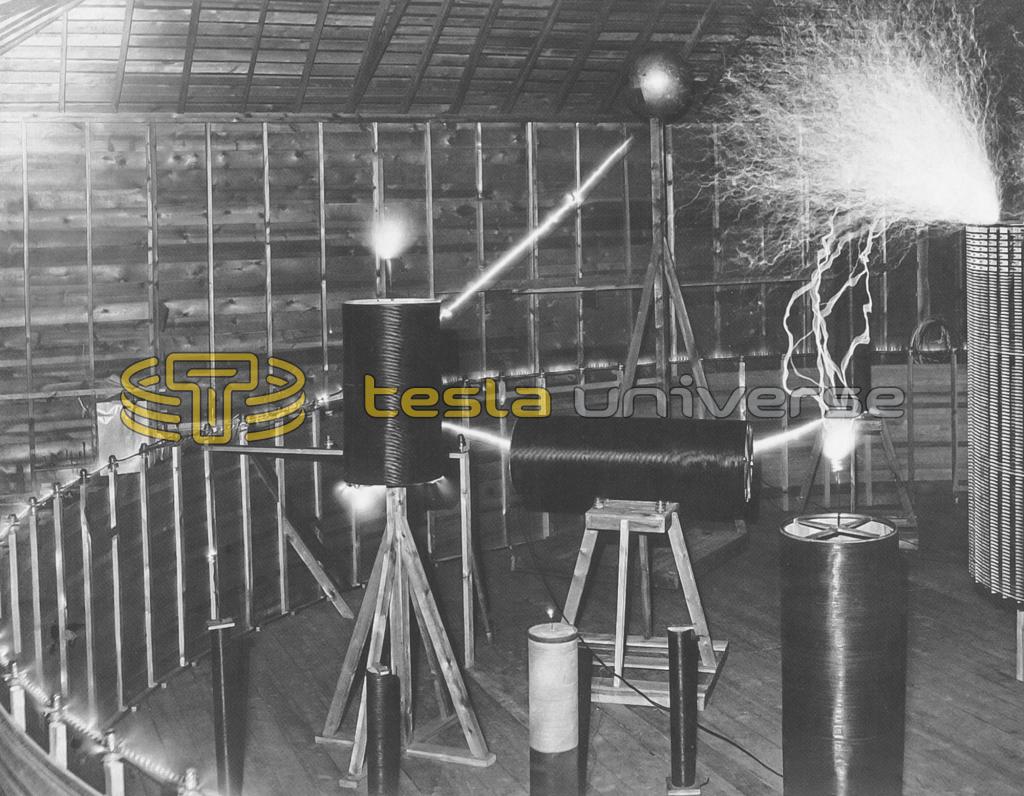
In any type of Tesla coil, the spark gap becomes a critical component in which any improvement results in an output boost as well as frequency stabilization. This necessary evil received a lot of attention by Tesla in his quest to perfect this troublesome device. In smaller coils, tubes are used to eliminate the gap. Obviously this is not possible for Magnifying Transmitters. Tesla used a rotary gap that gave 5000 breaks per second. Golka's transmitter uses both a breakwheel and quench gap.
The break wheel on the Leadville coil runs at 7000 RPM. Each tungston wheel is about 35" in diameter. These wheels are painstakingly cut in a sawtooth pattern out of circular "blanks." Then each one must be carefully balanced. The break wheel is driven by a single speed 40 horsepower motor. To give some idea of the air drag during operation, it was estimated that a 36" inch would require a 50 horsepower motor.


In series with the break wheel is a quench gap. The quench gap consists of two 1" diameter tungsten electrodes encased in an airtight, pressurized container containing a gas mixture. During operation, the operator controls the blend of gases which gives the operator a degree of control over the length of the sparks. The tungsten electrodes are quite strong and wear surprisingly well.
Primary Coil
In Tesla's giant coil, he had a 20-turn variable tuning coil connected to the the primary. The primary itself consisted of two turns of a heavy insulated cable placed along the base of the secondary framework. This wooden framework was erected in a circular pattern with a diameter of 51 feet.


In his experimental setup, Golka has built his primary similarly to Tesla. For instance he also uses cable - 600MCM - and mounts it along the base of the secondary. However, in his early experiments, Robert learned that wood does not last long in high voltage environments. Hence, in Colorado, he has converted his framework to plastic piping, a luxury Tesla did not have.
Secondary Coil
The secondary/primary combination in Tesla's transmitter dominated the site. The secondary wire was mounted on the framework above the primary. Once the wire had been strung, it resembled a 51' diameter corral that took up most of the space in the lab. In Tesla's version, 24 turns of #8 wire was used.
As in Tesla's lab, the primary/secondary combination dominates the workspace. Golka uses #6 wire for his secondary coil. A quick calculation should impress on any observer the sheer magnitude of the task of "winding" this secondary. Considering a 51' diameter, pi times diameter will give the length of one turn (about 160'). Multiply that result by the number of turns - 18 in Golka's coil - to get the total length of the secondary (about 2880' or roughly 1/2 mile!!).
Extra Coil
The "extra" coil is what gives the Magnifying Transmitter its punch. Tesla experimented a number of extra coils. The final revision consisted of 100 turns of #8 wire with an 8' diameter and was 12' high. Golka's extra coil uses #6 wire and stands about 25' high. For transporting the coil around the site, an overhead crane is used.
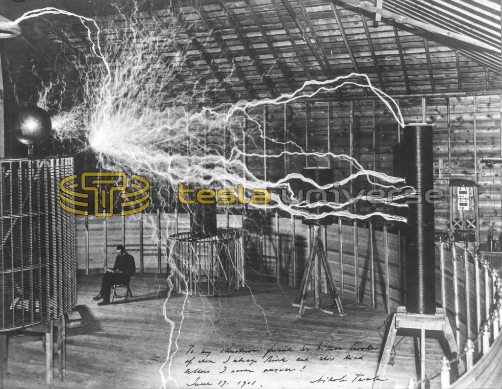
Many photos of Tesla's lab show Nikola Tesla fearlessly sitting next to his extra coil, inside of his primary/secondary. Please, don't try this!! What is really happening is trick photography. It was a common practice to subject the photographic plates to multiple exposures. When the coil was running, the area was evacuated and the spectacular sparks photographed. Later, Tesla would go sit in the chair, thus producing a "special effects" photo that even Hollywood would be proud of. Is it any wonder that early Frankenstein movies made a point to include the dreaded electric laboratory - probably modeled after Tesla's!
Elevated Capacitance
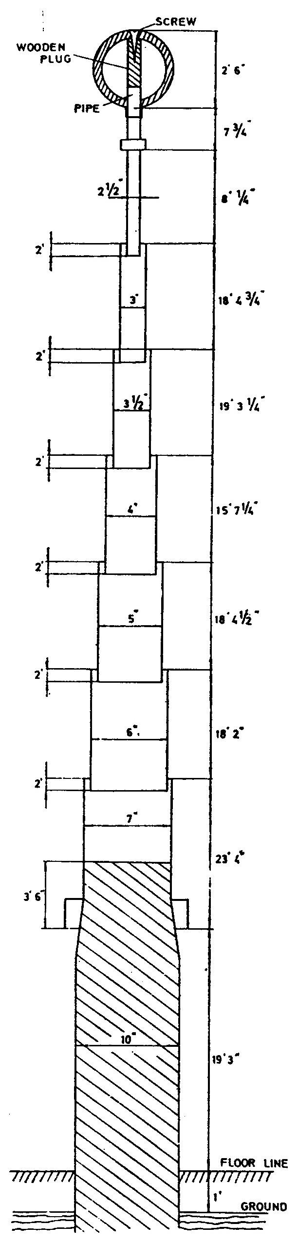
Tesla had a 142' tower with a 30" conductive ball mounted on it for an antenna. Once again, explicit construction details can be found in the Colorado Springs Notes. On page 226, a list of supplies used in building the elevated capacitance are listed. The care used in building the capacitance are underscored by Tesla's instructions for the ball...
On the top was supported a ball of 30" diam. hollow wood covered with tin foil very smoothly and the joints indented so as to have no conducting points sticking out.
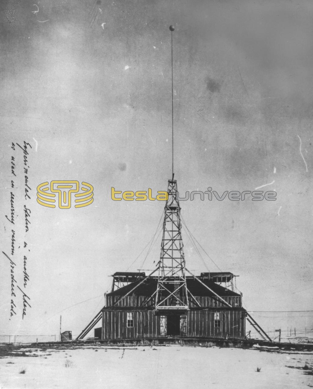
In the Leadville setup, just outside of the building housing the Tesla Magnifying Transmitter, a 150' telescoping tower has been erected. It also has a 30" conductive ball. A corona cone has been added to Golka's tower as a Faraday shield to prevent stray currents from being induced in the wooden segment of the tower. Such currents would have the potential to ignite the tower.


Perhaps the most perplexing problem involving the Wireless Power Transmission is the connection of the elevated capacitance to the extra coil. A number of configurations have been tried, but still the search continues. To date, direct connection, a 6' spark gap and a custom made vacuum tube has been tried. It seems that the elevated capacitance is so large that it drags the coil down when loaded. A lot more research is needed into this aspect of Tesla's work.
SAFETY, SAFETY and MORE SAFETY!
Perhaps the most striking fact about the equipment is the sheer size. Work on this size of coil requires plenty of common sense, a lot of muscle and extreme attention to detail. Even what may seem to be a minor snafu, like a loose wire, can have repercussions that are life threatening as well as expensive. After all, a loose "hot" wire can act as a cutting torch if it falls to a grounded item or fry an unwary (and hapless) bystander.
At the voltages and currents created during the operation of the coil, all parts are subjected to intense electrical and mechanical stress. Due to such stresses, some of the most hazardous situations occur from the least expected source. For example, the quench gap uses a mixture of gases under pressure and in the presence of an electrical arc. The most common failure with this component is that the ceramic mounts literally explode due to electrical overstress. This is the reason for the high impact plastic barrel encasing the unit.
Mechanical components have their own risks inherent in them. The rotating breaker wheel is mechanically equivalent to a number of saw blades all mounted on a single shaft. Imagine the destruction that would result if the shaft broke loose or a tip flew off the one of the blades while it was rotating at 7000 RPM.
It doesn't take a rocket scientist to see that all of the equipment needs to be "ruggedized," encased when possible, and strict safety precautions observed at ALL times. Safety is a primary concern in all phase of the operation, even when the coil itself is shutdown. (Note: in Figure 3, Robert Golka is shorting all capacitors to insure that he does not receive an "unpleasant surprise" while working on other parts of the coil!)
Results and Future Plans
The status of Project Tesla at this late date is somewhat hazy. In the past year, the main coil and the extra coil has been on-line and the elevated capacitance has even been connected on a couple of occasions. Measurements concerning power transmission have not been made due to the problems connected with the elevated capacitance. Currently, the main project itself is in limbo due to the intense cold at the site. There are some ongoing small experiments in Massachusetts for the purpose of perfecting the extra coil to elevated capacitance connection.
The future of Project Tesla is dependent to a large part on a rejuvinated working budget and volunteers. In the past, Project Tesla was operated on government grants, contracts, donations and Robert Golka's personal finances. To continue the main research, additional funding is required. The funding goes to the site rent, operation of the site, equipment replacement and upgrade, food and lodging (which is on site.) The project is a private venture and is not affiliated in any way, manner or form with the International Tesla Society. Additionally, the project does NOT enjoy a non-profit status which makes it difficult to raise funds.
The size of the equipment and the dangers inherent in the operation of this equipment imposes a need for skilled and alert labor force. In the past, the project relied on a pool of interested and dedicated volunteers. It will continue to do so in the future.
If you are seriously interested in working on a project of this magnitude or are interested in help funding this project, contact:
Project Tesla
PO Box 676
Brockton, MA 02401
United States of America
Due to the hazardous nature of this work and limited time, sightseeing is not allowed and unauthorized visitors are turned back at the gate.
Acknowledgments
I would like to thank Robert Golka for extending an invitation to examine the coil and for assisting me in writing this article by providing many of the technical details pertaining to his coil.
FOR MORE INFO
[1] George Trinkhaus, Tesla Coil, Claremont, CA: High Voltage Press, 1987.
[2] George Trinkhaus, Tesla: The Lost Inventions, Claremont, CA: High Voltage Press, 1988.
[3] Nikola Tesla, Colorado Springs Notes, Beograd, Yugoslavia: Nolit, 1978.
[4] Steven Elswick (editor), Proceedings of the 1986 Int'l Tesla Symposium, Colorado Springs, CO: International Tesla Society, Inc., 1986.
