
Nikola Tesla Articles
Mr. Tesla's Circuit Interrupters
For the production of intermittent currents for use in obtaining oscillatory currents of very high frequency by means of charging a circuit possessing capacity and self-induction, Mr. Nikola Tesla has designed a large number of interrupters or make and break devices embodying many ingenious features. These interrupters, or, as Mr. Tesla calls them, circuit controllers, were patented in a group of patents issued August 16, 1898.

In order to make clear the purpose of these devices it may be well to give an untechnical explanation of the means of producing high frequency or oscillatory currents. Whenever a charged condenser is short circuited through a circuit containing self-induction the sudden rush of current, by an action analogous with mechanical inertia, over-discharges the condenser, charging it up in the reverse direction; this again discharges the other way, again reversing the charge in the condenser, and so on, the oscillations gradually dying out at a rate dependent on the resistance of the circuit. With ordinary Leyden jars and the small self-induction obtained by a few turns in air, these oscillations have a frequency of several hundred thousand alternations per second, this frequency running up as the capacity of the condenser or the amount of the self-induction is diminished, being, in fact, inversely proportional to the square root of the product of the capacity and the self-induction. To start such an action the condenser must first be charged and then closed on its discharge circuit. The simplest way of accomplishing this, and the means most commonly used, is to insert a spark gap in the circuit and in shunt with this spark gap connect the secondary of a high-voltage transformer supplied with ordinary alternating current, or the secondary of an induction coil. The action, then, is as follows: As the voltage rises in the transformer the condenser is gradually charged until the pressure gets so high that it jumps across the spark gap. The spark or arc here formed is of such a low resistance that the condenser and its discharge circuit are practically short circuited through it, and the oscillations continue for a short while, until the arc dies out, the action being repeated at the next reversal of the alternating current supplied.
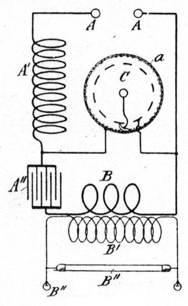
Such a method is extremely wasteful of power, for two reasons. First, because the secondary of the transformer is short circuited just at the peak of the wave; and, second, because the arc or spark offers some resistance to the high-frequency oscillations, which, therefore, die out more quickly than they would if they were not opposed in this way. A far better plan, therefore, is the use of a mechanical interrupter, such as those described below, the action of which can best be understood by a reference to Fig. 3. Here A A are the terminals of the source of supply, which may be either direct or alternating current at commercial pressures, 100, 200, 500 or 1000 volts. A' is a highly inductive coil which should be wound on iron. A" is the condenser, B a small self-induction, and C the interrupter. The action is as follows: When the circuit is open at C, the pressure applied from the source of supply acts through A' and B to charge the condenser, A". Suddenly A" and B are short circuited through the interrupter, C, and the condenser discharges with oscillations, occurring perhaps several hundred thousand times per second. These gradually die out, becoming negligible after perhaps 200 or 300 oscillations, when the circuit is suddenly opened again at C. It should be noted that C, besides short circuiting the condenser through its slight self-induction, B, has also short circuited the source of supply connected to the terminals, A A, through the inductive coil, A'. This short circuit is so brief, however, that the incoming current has not had time to rise to an undesirable strength, but has been held back by the self-induction of A'. It has also while rising been storing up, so to speak, a certain amount of energy in the magnetic circuit of A'. Now, when the circuit at C is again opened, this current, passing through A', tends to persist, owing to the self-induction therein, and charges the condenser A" up to a voltage considerably higher than that of the source of supply, the energy absorbed in the magnetic circuit of A' passing out thus into the condenser A", charging it to a high voltage, the interrupter, C, afterward short circuiting this and allowing the current to oscillate again through the discharge circuit, B.

Thus the interrupter, C, inductive coil, A', and the source of supply act to open the condenser circuit for a brief instant and charge the condenser by a sort of electrical blow, immediately short circuiting it again and allowing it to discharge in oscillations. If the condenser discharge circuit is tuned to a frequency of, say, 300,000 per second, and its resistance is such that 300 oscillations take place before they die down to a negligible value, the interrupter, C, should make and break the circuit about 1000 times a second. There will then exist in the condenser discharge circuit, B, a cycle somewhat as follows: A sudden surging charge followed by an oscillatory discharge, starting with high waves, which gradually die down until interrupted by the next surging charge, etc. Owing to the enormous frequency of these oscillatory discharges, they can be transformed by ordinary double-winding, stationary alternating transformers, with a very small amount of material for their capacity, since the capacity of any transformer is proportional to the rate of change of lines of force, and is hence proportional to the frequency of the alternating currents therein. So high is this frequency, that an air magnetic circuit is all that is necessary, iron, in fact, being a disadvantage, owing to the energy lost within it in eddy currents and hysteresis, with such a high frequency. In the figure, B represents the primary of such a high-frequency air transformer. B' being the secondary, with a winding of more turns to obtain higher tension, the output of which is delivered to any translating devices, as B".
The distinguishing feature of the devices described below is the use of a liquid for one or both of the contacts of the make and break devices, this liquid preferably being mercury, acting in some instances in the form of a jet and in other cases as a surface with which a solid conductor makes and breaks a contact. Ingenious applications are also made of other principles, such as the use of a liquid dielectric between the contacts, inert gases under high pressure, jets meeting each other, etc.; and all the instruments are worked out with great perfection of detail for continuous and practically frictionless running, such as to require a minimum of attention.
The requirements of such an instrument are well stated in the patent specifications, as follows: The capability of effecting an extremely rapid interruption and completion of the circuit, the latter being positive and abrupt; the apparatus not to be liable to derangement, and capable of prolonged use without attention or adjustment.
Of the various types described the first is that shown in cross section in Fig. 1. This consists of an inclosing shell, F, arranged to be rapidly rotated by means of a motor coupled to the shaft shown at the left, and containing two liquids of different specific gravities, that with the higher specific gravity being a conductor and the other an insulator; preferably the conductor is mercury, the insulator being some hydrocarbon. When the shaft and shell mentioned are rapidly rotated the mercury flies to the periphery by centrifugal force and forms a ring shown at R, the other liquid forming an inner ring, as shown at S. Within the shell is an arm, L, supported on a non-rotating shaft, H, carrying a wheel, M, with projecting points sufficiently long to touch the mercury, R. As the liquids revolve they rotate this wheel at high speed, the points of which successively and repeatedly dip into the mercury rim and leave it again, the relative motion being a hypo-cycloid. The insulating liquid, under considerable pressure, owing to centrifugal action, forces itself between the mercury and the points as the latter recede and extinguishes the arcs which tend to form across these gaps. Other figures attached to the same patent show the machine assembled with a motor, condenser and transformer.

The next patent describes the waste of energy which occurs during the periods of make and break, or both, due to the passage of the current through an arc formed between the terminals; this loss of energy is said to be generally such as to render impossible a practical and economical conversion of considerable amounts of electrical energy by means of ordinary make and break devices, particularly in cases where a high frequency is required. Experiment and investigation have led Mr. Tesla to recognize the following laws governing this waste of energy: First, that the loss in any device for making and breaking a circuit, other conditions being the same, is inversely proportional rather to the square than to the first power of the relative velocity of the terminals in approaching and receding from one another in case the current curve is not so steep as to materially depart from one which may be represented by a simple sine function of the time; but such a case seldom obtains in practice; on the contrary, the current curve resulting from a make and break is generally very steep and particularly so when the circuit controller effects the charging and discharging of a condenser, and consequently the loss of energy is still more rapidly reduced by increased velocity of approach and separation.
With a view to securing an interrupter in which not only the relative speed of the terminals but also the frequency of the interruption should be very high, the instrument shown in Fig. 2 was designed; this consists essentially of a shell, a, attached to the external armature, f, of a direct-current motor with a commutator, g, and field magnets, d, by which means the shell, a, is rotated at high speed on a self-oiling spindle, c. Projecting downward from the upper lid of the shell is a series of teeth, l, and within the case is a nozzle, k, arranged to throw a jet of mercury against these teeth; the nozzle is attached by means of an arm, i, to an armature, h, which is prevented from rotation by means of the field of force of an external non-rotating magnet, o, this field acting through the shell of the rotating case on the armature within. When mercury is placed within this case and the latter is revolved the mercury rises by centrifugal force against the outer wall and is caught by an open mouth or scoop attached to the non-rotating nozzle, k, and directed by the latter against the teeth, l. The main circuit is open between this nozzle and these teeth, and is intermittently closed by the jet of mercury.
For the further reduction of arcing others have used contacts made in a high vacuo, but Mr. Tesla claims that only a moderate improvement is secured in this manner, and this can be greatly exceeded by the use of certain fluids inert chemically maintained at a high pressure in the make and break chamber. It is found that in such a case the arc, when formed, is restricted to a small cross section or is, in other words, prevented from expanding laterally, and is therefore more quickly raised to a high resistance, choking back the current to such an extent that the arc is more promptly extinguished.

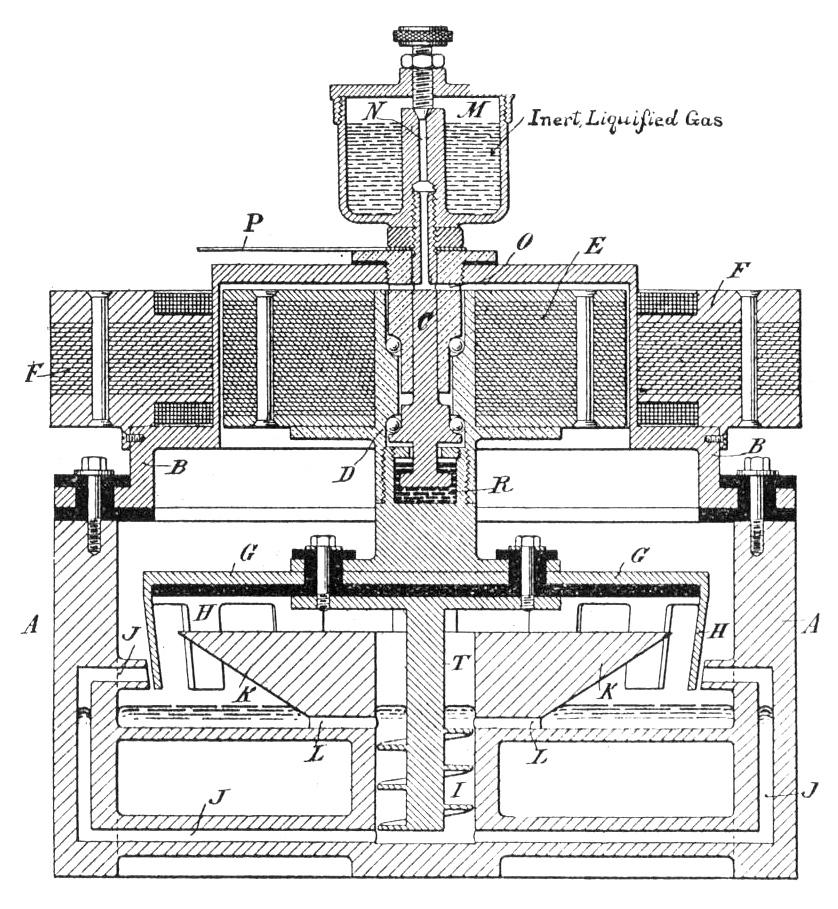
Fig. 4 shows an apparatus designed to make use of this principle. Here F is the laminated field ring or primary of a rotary field motor, the secondary of which is wound upon the rotatable core, E, mounted on the shaft, D, within the gas-tight shell, A, which is closed by the insulated and gas-tight cover, B. The rotating field of force obviously acts through the shell, B, which should be an insulating material or high-resistance metal, and rotates the parts within which carry a crown of downwardly projecting teeth, H, and on the lower end of the shaft a screw pump, I. This screw pump acts upon the mercury in the lower part of the vessel, forcing it outwardly through tubes, J, from which it emerges in jets against the teeth, H; these jets and teeth make and break the circuit as in the apparatus described above, the whole being kept under pressure by an inert fluid shown in the cup, M, at the top of the apparatus; this liquid may be such a one as anhydrous ammonia, giving, at ordinary temperatures, a high pressure, due to its restricted evaporation and low boiling point. The gas is carried down into the chamber through the tube, N, in the fixed internal part of the ball bearing, C.

A means of accomplishing the same result without the use of a magnetic field acting through a fixed gas-tight wall, utilizing instead the force of gravity, is shown in Fig. 5, where A is again a gas-tight case supported upon an inclined spindle, B, and arranged to be rotated by a direct-current motor with outside armature similar to that shown in Fig. 2. Within this case is an eccentric weight, K, mounted on a self-oiling spindle, J, with a ball thrust bearing to avoid its being dragged around by friction. Owing to the inclination of the rotating axis of the system from the vertical, this weight, K, tends to remain at the low side and not to revolve with the case. Attached to this non-rotating weight, K, is an arm, L, carrying another ball bearing shaft, N, supporting a number of vanes, Q. When the case is revolved the mercury contained therein is maintained by centrifugal force in the form of a ring against the outside wall, into which ring the vanes, Q, dip and are rotated at high speed, making and breaking a contact between themselves and the mercury.

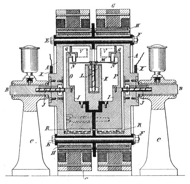
Still another device for obtaining a rapid make and break in a gas-tight chamber, this time utilizing both the rotary field and the eccentric weight, is shown in Fig. 6, where G G are two stationary primaries of the induction motor, which in this case is arranged in a vertical plane of rotation, H H being two secondary rotors, the necessity for two elements being the division of the rotating part by insulating gaskets into two sections. Within this rotating chamber, A, are mounted two eccentric weights, I I, fastened together by an insulating joint and supported on the spindles, J J. Fastened also to them is the central vertical journal, K, in which rotates the spindle, L, carrying a wheel, M, and inclined helically bent blades, N N. As before mercury placed in the revolving case is carried around by centrifugal force and, meeting the spouts attached to the nozzles, Q, is driven by its own inertia through them against the blades, N N, which, owing to their inclination, are given a rapid rotary motion about the spindle, L. The claims of novelty made for this combination are the facts that the action of the jets themselves puts in motion the solid terminals of the make and break device, with a speed very high compared with that of the shell, and that the motion of the vanes acts gyroscopically to prevent oscillation (and hence variation of the frequency) of the eccentric weights, I I.

A similar make and break device, in which, however, both terminals are liquid jets, is shown in Fig. 7. Here, as in Fig. 6, are the two rotary field motors rotating in a vertical plane with eccentric weights, K K', the scoop attached to the former directing a jet from the nozzle, L'. The scoop attached to the other is intended to direct the liquid through the tube, M, to the axis of rotation, whence it is distributed through passages in the rotating case to the nozzles, O O. These jets striking that from L' make and break the circuit between the two insulated halves of the shell, thus giving liquid contacts at both terminals of the make and break device.
Another interesting variation of the inclined axis arrangement shown in Fig. 5, giving mercury terminals in another way, is shown in Fig. 8, the essential features of which are a rotating shell, A, eccentric weight, J, carrying a tube, P, with scoop and nozzle and an unbroken solid metal terminal, M, with which the mercury makes contact. Rotating with the shell is a crown of downwardly projecting teeth, O O, these teeth being in this instance insulators preferably non-organic and vitreous. These insulating teeth cut off the stream of mercury intermittently, giving a rapid make and break with mercury terminals.

A further modification by which higher frequency is obtained is shown in Fig. 9, the frequency being doubled by means of rotating both terminals of the make and break device in opposite directions. This is effected by means of one rotary field generated by the primary, H, actuating the rotatable secondary, G, which carries on spindle, C, the gas-tight shell, D, through the upper part or cap of which, F, still another rotary field acts upon the secondary wound upon Q, which in turn is rotatable on spindle, P, and carries by means of arms, T, the mercury scoops and jets, V. These move in one direction while the teeth, L L, rotate with the case, D, in the opposite direction, thus giving double the frequency obtainable with the same angular velocity and one member stationary.
A most curious modification is shown in Fig. 10, in which the winding of the secondary of one of the elements, instead of being a copper short-circuited squirrel cage, as in the induction motors described above, consists of the mercury itself, this being arranged in two rings, B B', forming the two terminals. A powerful rotating field, generating Foucault currents in these rings, will rotate them with a high velocity, the field completing itself through the stationary core, E'. Above is another rotary field actuating the secondary, N', which carries the star wheels, L' L", whose teeth dip into the mercury rings below. The element carrying these wheels is supposed to rotate in the opposite direction from the rings of mercury, giving the star wheels a high peripheral velocity and a correspondingly high frequency of make and break.
Another patent issued simultaneously with those described above and by the same inventor covers an improvement in electrical igniters for gas engines, as shown in Fig. 11, the principle being the use of an oscillatory discharge in the cylinder of the engine, the primary impulse being obtained at the proper instant from a contact actuated by the motion of the engine parts.
In the figure, E is the source of current, H an inductive coil, G a condenser, and K the transformer; at a is shown the contact for short-circuiting the primary and condenser at the proper time, thus causing a discharge from the secondary between the terminal, L, and the piston, B.
Remarkably broad claims on these various mechanical combinations have been obtained, the most important being briefly as follows: a rotating receptacle and independently mounted terminal, making contact with the fluid therein; a jet making contact with spaced conductors in combination with self-contained means for maintaining a circulation of the fluids (the use of a jet contact being well known in the art was not broadly patentable); an interrupter surrounded in a closed receptacle by an inert insulating medium under pressure; the use of jets for both terminals and the use of a jet intercepted intermittently by insulating solids.
