Nikola Tesla Articles
Nikola Tesla's Electrolytic Meter 2
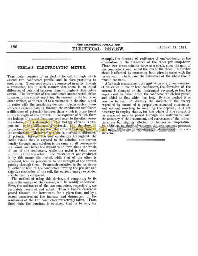
This meter consists of an electrolytic cell, through which extend two conductors parallel and in close proximity to each other. These conductors are connected in series through a resistance, but in such manner that there is an equal difference of potential between them throughout their entire extent. The terminals of the conductors are connected either in series in the circuit supplying the current to the lamps or other devices, or in parallel to a resistance in the circuit; and in series with the translating devices. Under such circumstances a current passing through the conductors establishes a difference of potential between them which is proportional to the strength of the current, in consequence of which there is a leakage of current from one conductor to the other across the solution. The strength of this leakage current is proportional to the difference of potential, and therefore, in proportion to the strength of the current passing through the conductors. Moreover, as there is a constant difference of potential between the two conductors throughout the entire extent that is exposed to the solution, the current density through such solution is the same at all corresponding points, and hence the deposit is uniform along the whole, of one of the conductors, while the metal is taken away uniformly from the other. The resistance of one conductor is by this means diminished, while that of the other is increased, both in proportion to the strength of the current passing through them. From such variation in the resistance of either or both of the conductors forming the positive and negative electrodes of the cell, the current energy expended may be readily computed.
The method of using this device, and computing by its means the energy of the current, will be readily understood. First, the resistances of the two conductors, respectively, are accurately measured and noted. Then a known current is passed through the instrument for a given time, and by a second measurement the increase and diminution of the resistances of the two conductors respectively taken. From these data the constant is obtained, that is to say, for example, the increase of resistance of one conductor or the diminution of the resistance of the other per lamp-hour. These two measurements serve as a check, since the gain of one conductor should equal the loss of the other. A further check is afforded by measuring both wires in series with the resistance, in which case the resistance of the whole should remain constant.
After each measurement or registration of a given variation of resistance in one or both conductors, the direction of the current is changed or the instrument reversed, so that the deposit will be taken from the conductor which has gained and added to that which has lost. By this method it is possible to read off directly the amount of the energy expended by means of a properly-constructed ohm-meter, and without resorting to weighing the deposit; it is not necessary to employ shunts, for the whole of the current to be measured may be passed through the instrument; and the accuracy of the instrument, and correctness of the indications, are but slightly affected by changes in temperature. In addition to these advantages the arrangement possesses the merit of economy of energy, and simplicity in construction.
