Nikola Tesla Articles
The Swinburne "Hedgehog" Transformer
Last year Mr. James Swinburne brought forward the theory that an open iron circuit could be made more efficient than any form of closed iron circuit transformer. The loss in a transformer, he argues, is made up of loss in copper due to resistance, and loss in iron due to hysteresis. In calculating the efficiencies of transformers, the loss in the iron has generally been left completely out of account, and the loss in copper alone considered; hence, the efficiencies of 97 and 98 per cent. claimed for closed iron circuit forms. If the loss by hysteresis is taken into account, allowing the losses as given by Ewing, the loss in iron in closed circuit transformers, as usually designed, is some 10 per cent. of the full load. As the loss in iron goes on all the time a transformer is in circuit, this is very serious. The proportion of actual to possible output of energy per day varies in different districts, but in most stations the average use of lamps is less than two hours a day, including all lamps installed. The transformer must be large enough to feed all the lamps installed, so it runs, say, on an average two hours at full load a day. If there is a loss of 10 per cent. at full load in the iron, this gives an actual efficiency of 45.5 per cent., even neglecting the loss in copper.
In the "hedgehog" form the proportion of iron is very much reduced. The cross section of the iron is much less, and the length is about one-third of that of the closed circuit form, as it has not to surround the wire. The result is that even in small transformers the iron loss is under one per cent. of the full load. One per cent. of the full load gives 89 per cent. all day efficiency, neglecting copper loss, against the 45 per cent. of the closed circuit. This is neglecting copper, however, and the copper loss is greater in the "hedgehog" form, so this is an exaggerated comparison. Such a transformer in reality, according to Mr. Swinburne, has an efficiency of about 87 per cent. all day.
The theory of the "hedgehog" form is this: If a closed iron circuit is used, the iron circuit must be long to embrace the copper coils. The only way to shorten it is to make the copper coils smaller. This means using a higher current density, which is wasteful, or fewer turns of copper. Fewer turns of copper demand either a higher induction in the iron or a greater cross section, and either of these means greater loss by hysteresis. If the iron circuit is opened, the sides of the embracing core can be removed, so the loss by hysteresis is divided by three. As there is now plenty of room for the copper, the turns and cross section can be increased and the iron reduced still farther.
The object of introducing the closed iron circuit was to reduce the magnetic resistance. An open circuit transformer has much higher magnetic resistance, but, according to Mr. Swinburne, the question of magnetic resistance is not so important as might at first sight appear. Its increase demands more excitation, or more magneto-motive force, and this increases the loss in copper. The best form is thus a compromise, and the "hedgehog" ends are employed to reduce the magnetic resistance. In a conductive circuit the resistance is low if the current density is low in all parts where the specific resistance is high. Similarly, in a composite magnetic circuit of iron and air, the magnetic resistance is low if there is never a high magnetic current density or induction in the air, which has high specific magnetic resistance. The magnetizing current in a "hedgehog" is high, but as it is a quarter of a period behind the primary current in phase, and as the primary wire has to be large enough to carry the primary current, the loss in watts is small. As this loss goes on all day, however, it is by no means unimportant, and has to be included in getting out the efficiencies of these transformers.
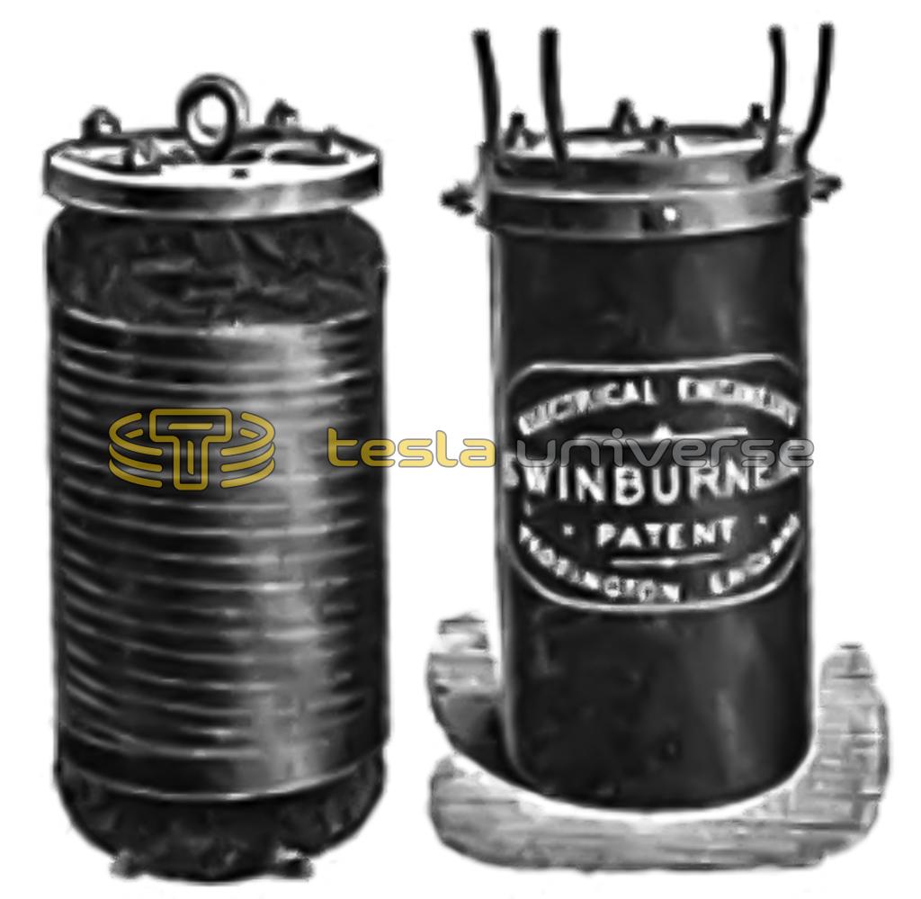
The construction of these transformers as carried out by Messrs, Swinburne & Co., of Teddington, England, is very simple. A gun metal casting of cross shaped section forms the backbone. It is spread out at each end, forming legs at one and taking the circular terminal board at the other. It also carries insulating flanges, which form the ends of the coils. Into the four recesses of the core are put four bundles of soft iron wire. These are taped over, and the secondary is wound on. The secondary is then covered with two layers of ebonite, and the flanges are also faced with the same material. The primary is then wound on in two compartments separated with ebonite after the manner invented by Gramme, so that both ends come outside, and as far removed from each other as possible. The ends of the core are then spread out, as shown in Fig. 1, and the transformer tested under 4,000 or 5,000 volts, the insulation in megohms being read by a peculiar instrument which measures the effective resistance under an alternating current.
Iron cases cannot be used, as they would be magnetized by the transformer; and, as any metal would have Foucault currents generated in it, stoneware jars are used for cases. These have lids bolted down, with holes for the leads, as shown in the engraving, Fig. 2.

