Nikola Tesla Articles
Tesla's Electrical Oscillators
The important researches and experiments which Nikola Tesla has been carrying on for years, and which have created such a widespread interest in the scientific world, have culminated in the production of thoroughly practical and efficient electrical oscillators or transformers for the conversion of ordinary direct or alternating currents into electrical vibrations of any desired frequency. In five patents, granted to him September 22, 1896, he shows typical forms of his apparatus as adapted to any of the usual sources of supply. The remarkably clear and simple description of the features involved makes it perfectly easy for any one to understand the operation of these most valuable appliances.
The numerous uses to which these high-frequency transformers can be put will, we believe, cause their rapid and extensive introduction, and it is difficult to estimate the benefit which will result to science and industry from their applications. For lighting with phosphorescent bulbs or tubes, for the production of Roentgen phenomena, for the manufacture of ozone, argon and such bodies, for electro-therapeutic employment, and many uses for which induction coils are suitable, they afford ideal instruments. New applications will no doubt be found, but it is very probable that their chief employment will be for purposes of lighting by high-frequency currents, in which Tesla is the recognized pioneer.
We quote the exact language of the inventor in describing a few forms of his appliances for high-frequency phenomena:
"The object of my present improvements is to provide a simple, compact and effective apparatus for producing these effects, but adapted more particularly for direct application to and use with existing circuits carrying direct currents, such as the ordinary municipal incandescent lighting circuits. The way in which I accomplish this, so as to meet the requirements of practical and economical operation under the conditions present, will be understood from a general description of the apparatus which I have devised. In any given circuit, which for present purposes may be considered as conveying direct currents or those of substantially the character of direct or continuous currents, and which, for general purposes of illustration, may be assumed to be a branch or derived circuit across the mains from any ordinary source, I interpose a device, or devices, in the nature of a choking coil, in order to give to the circuit a high self-induction. I also provide a circuit controller of any proper character that may be operated to make and break said circuit. Around the break, or point of interruption, I place a condenser, or condensers, to store the energy of the discharge current, and in a local circuit, and in series with such condenser, I place the primary of a transformer, the secondary of which then becomes the source of the currents of high frequency. It will be apparent from a consideration of the conditions involved that, were the condenser to be directly charged by the current from the source, and then discharged into the working circuit, a very large capacity would ordinarily be required, but by the above arrangement the current of high electro-motive force, which is induced at each break of the circuit, furnishes the proper current for charging the condenser, which may, therefore, be small and inexpensive. Moreover, it will be observed that, since the self-induction of the circuit through which the condenser discharges, as well as the capacity of the condenser itself, may be given practically any desired value, the frequency of the discharge current may be adjusted at will.
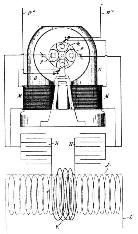
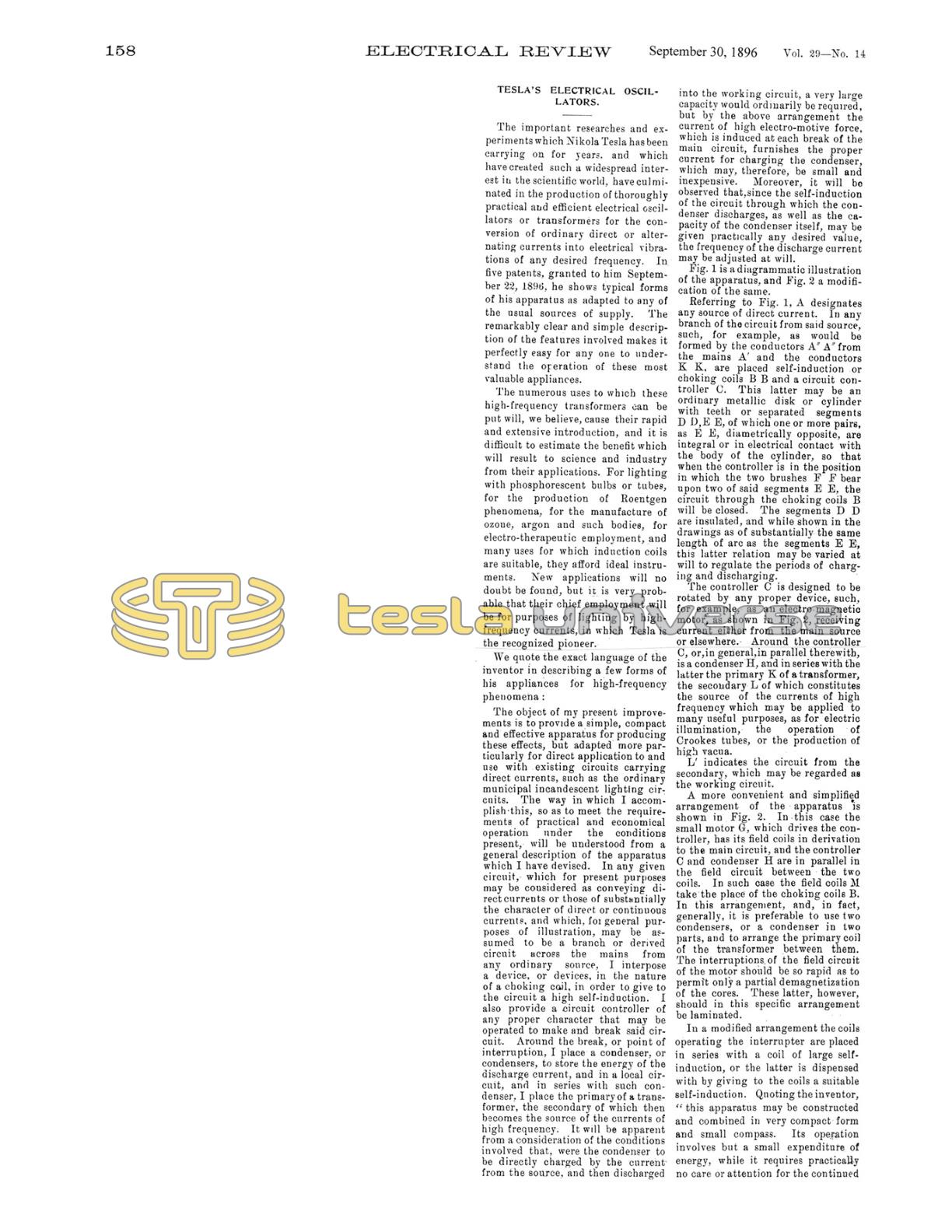
Fig. 1 is a diagrammatic illustration of the apparatus, and Fig. 2 a modification of the same.
Referring to Fig. 1, A designates any source of direct current. In any branch of the circuit from said source, such, for example, as would be formed by the conductors A' A from the mains A'' and the conductors K K, are placed self-induction or choking coils B B and a circuit con- troller C. This latter may be an ordinary metallic disk or cylinder with teeth or separated segments D D, E E, of which one or more pairs, as E E, diametrically opposite, are integral or in electrical contact with the body of the cylinder, so that when the controller is in the position in which the two brushes F F bear upon two of said segments E E, the circuit through the choking coils B will be closed. The segments D D are insulated, and while shown in the drawings as of substantially the same length of arc as the segments E E, this latter relation may be varied at will to regulate the periods of charging and discharging.
The controller C is designed to be rotated by any proper device, such, for example, as an electro-magnetic motor, as shown in Fig. 2, receiving current either from the main source or elsewhere. Around the controller C, or, in general in parallel therewith, is the condenser H, and in series with the latter the primary K of a transformer, the secondary L of which constitutes the source of the currents of high frequency which may be applied to many useful purposes, as for electric illumination, the operation of Crookes tubes, or the production of high vacuum.
L' indicates the circuit from the secondary, which may be regarded as the working circuit.
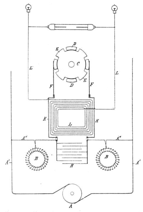
A more convenient and simplified arrangement of the apparatus is shown in Fig. 2. In this case the small motor G, which drives the controller, has its field coils in derivation to the main circuit, and the controller C and condenser H are in parallel in the field circuit between the two coils. In such case, the field coils M take the place of the choking coils B. In this arrangement, and, in fact, generally, it is preferable to use two condensers, or a condenser in two parts, and to arrange the primary coil of the transformer between them. The interruptions of the field circuit of the motor should be so rapid as to permit only a partial demagnetization of the cores. These latter, however, should in this specific arrangement be laminated.
In a modified arrangement the coils operating the interrupter are placed in series with a coil of large self-induction, or the latter is dispensed with by giving to the coils a suitable self-induction. Quoting the inventor, “this apparatus may be constructed and combined in very compact form and small compass. Its operation involves but a small expenditure of energy, while it requires practically no care or attention for the continued production of ozone in unlimited amount."
Dwelling specifically upon the conversion of alternating or undulating currents, Mr. Tesla says:
When the potential of the source periodically rises and falls, whether with reversals or not is immaterial, it is essential to economical operation that the intervals of interruption of the charging current should bear a definite time relation to the period of the current, in order that the effective potential of the impulses charging the condenser may be as high as possible. I therefore provide, in case an alternating or equivalent electro-motive force be employed as the source of supply, a circuit controller which will interrupt the charging circuit at instants predetermined with reference to the variations of potential therein. The most practicable means for accomplishing this, of which I am aware, is to employ a synchronous motor connected with the source of supply and operating a circuit controller which interrupts the charging current at or about the instant of highest potential of each wave, and permits the condenser to discharge the energy stored in it through its appropriate circuit. This apparatus, which may be considered as typical of the means employed for carrying out the invention, I have illustrated in the accompanying drawings.
Referring to Fig. 3, A designates any source of alternating or equivalent current, from which lead off mains A' A'. At any point where it is desired to produce the high-frequency currents, a branch circuit B is taken off from the mains, and, in order to raise the potential of the current, a transformer is employed, represented by the primary C and secondary D. The circuit of the secondary includes the energizing coils of a synchronous motor E and a circuit controller, which, in the present instance, in Fig. 3, is shown as composed of a metal disk F with insulated segments F' in its periphery and fixed to the shaft of the motor. An insulating arm G, stationary with respect to the motor shaft and ad- justable with reference to the poles of the fixed magnets, carries two brushes H H, which bear upon the periphery of the disk. With the parts thus arranged, the secondary circuit is completed through the coils of the motor whenever the two brushes rest upon the uninsulated segments of the disk and interrupted through the motor at other times. Such a motor, if properly constructed, in well understood ways, maintains very exact synchronism with the alterations of the source, and the arm G may, therefore, be adjusted to interrupt the current at any determined point in its waves. It will be understood that by the proper relations of insulated and conducting segments and the motor poles, the current may be interrupted twice in each complete wave at or about the points of highest potential. The self-induction of the circuit containing the motor and controller should be high, and the motor itself will usually be constructed in such manner that no other self-induction device will be needed. The energy stored in this circuit is utilized at each break therein to charge a condenser K. With this object the terminals of the condenser are connected to the two brushes H H or to points of the circuit adjacent thereto, so that when the circuit through the motor is interrupted, the terminals of the motor circuit will be connected with the condenser, whereby the latter will receive the high-potential inductive discharge from the motor or secondary circuit.
The condenser discharges into a circuit of low self-induction, one terminal of which is connected directly to a condenser terminal and other to the brush H opposite to that connected with the other condenser terminal, so that the discharge circuit of the condenser will be completed simultaneously with the motor circuit and interrupted while the motor circuit is broken and the condenser being charged.
The discharge circuit contains a primary M of a few turns, and this induces in a secondary N impulses of high potential, which, by reason of their great frequency, are available for the operation of vacuum tubes P, single terminal lamps R, and other novel and useful purposes.
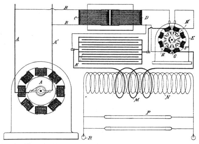
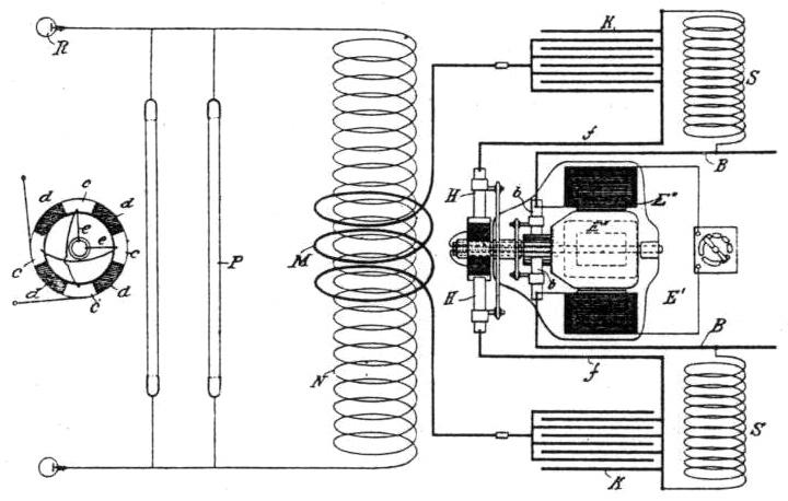
It is obvious that the supply current need not be alternating, provided it be converted or transformed into an alternating current before reaching the controller. For example, the present improvements are applicable to various forms of rotary transformers, as is illustrated in Fig. 4.
E' designates a continuous-current motor, here represented as having four field poles wound with coils E" in shunt to the armature. The line wires B B connect with the brushes b b bearing on the usual commutator.
On an extension of the motor shaft is a circuit controller composed of a cylinder, the surface of which is divided into four conducting segments c and four insulating segments d, the former being diametrically connected in pairs, as shown in detail in Fig. 4.
Through the shaft run two insulated conductors e e from any two commutator segments 90 degrees apart, and these connect with the two pairs of segments c, respectively.
With such arrangement it is evident that any two adjacent segments c c become the terminals of an alternating current source, so that if two brushes H H be applied to the periphery of the cylinder, they will take off current during such portion of the wave as the width of segment and position of the brushes may determine. By adjusting the position of the brushes relatively to the cylinder, therefore, the alternating current delivered to the segments c c may be interrupted at any point in its waves.
While the brushes H H are on the conducting segments, the current which they collect stores energy in a circuit of high self-induction formed by the wires f f, self-induction coils S S, the conductors B B, the brushes and commutator. When this circuit is interrupted by the brushes H H passing on to the insulating segments of the controller, the high-potential discharge of this circuit charges the condensers K K, which then discharge through the circuit of low self-induction containing the primary M. The secondary circuit N contains any devices, as P R, for utilizing the current.
In other arrangements, circuit controllers of special construction are shown mounted on the shaft of a generator, and a transformer is employed in connection to raise the tension of the supply current.
In regard to the regulation of his system Tesla says:
It is well known that every electric circuit, provided its ohmic resistance does not exceed certain definite limits, has a period of vibration of its own analogous to the period of vibration of a weighted spring. In order to alternately charge a given circuit of this character by periodic impulses impressed upon it and to discharge it most effectively, the frequency of the impressed impulses should bear a definite relation to the frequency of vibration possessed by the circuit itself. Moreover, for like reasons the period or vibration of the discharge circuit should bear a similar relation to the impressed impulses or the period of the charging circuit. When the conditions are such that the general law of harmonic vibrations is followed, the circuits are said to be in resonance or in electro-magnetic synchronism, and this condition I have found in my system to be highly advantageous. Hence in practice I adjust the electrical constants of the circuits so that in normal operation this condition of resonance is approximately attained. To accomplish this, the number of impulses of current directed into the charging circuit per unit time is made equal to the period of the charging circuit itself, or, generally, to a harmonic thereof, and the same relations are maintained between the charging and discharge circuit. Any departure from this condition will result in a decreased output, and this fact I take advantage of in regulating such output by varying the frequencies of the impulses or vibrations in the several circuits. Inasmuch as the period of any given circuit depends upon the relations of its resistance, self-induction, and capacity, a variation of any one or more of these may result in a variation in its period. There are, therefore, various ways in which the frequencies of vibration of the several circuits in the system referred to may be varied, but the most practicable and efficient ways of accomplishing the desired result are the following: (a) Varying the rate of the impressed impulses of current, or those which are directed from the source of supply into the charging circuit, as by varying the speed of the commutator or other circuit controller; (b) varying the self-induction of the charging cir- cuit; (c) varying the self-induction or capacity of the discharge circuit.
To regulate the output of a single circuit which has no vibration of its own by merely varying its period would evidently require, for any extended range of regulation, a very wide range of variation of period; but in the system described, a very wide range of regulation of the output may be obtained by a very slight change of the frequency of one of the circuits when the above mentioned rules are observed.