Nikola Tesla Articles
Tesla's New System of Electric Lighting
Incandescent Lamps without Return Circuit - Lighting by Condenser Discharge
We illustrate herewith an interesting system of electric lighting invented by Mr. Tesla, which is the outgrowth of the striking experiments described by him recently before the Institute of Electrical Engineers. The invention is based upon the discovery that an electric current of an excessively short period and very high potential may be utilised economically and practicably to great advantage for the production of light. As an instance of the lowest practicable limits, fairly good results have been obtained by a frequency as low as 15,000 to 20,000 per second, and a potential of about 20,000 volts. Both frequency and potential may be enormously increased above these figures, the practical limits being determined by the character of the apparatus and its capability of standing the strain.
To produce a current of very high frequency and very high potential, certain well-known devices may be employed. For instance, as the primary source of current or electrical energy a continuous-current generally may be used, the circuit of which may be interrupted with extreme rapidity by mechanical devices, or a magneto-electric machine specially constructed to yield alternating currents of very small period may be used; and in either case, should the potential be too low, an induction coil may be employed to raise it; or, finally, in order to overcome the mechanical difficulties, which in such cases become practically insuperable before the best results are reached, the principle of the disruptive discharge may be utilised. By means of this latter plan a much greater rate of change in the current is produced than by the other means suggested. The current of high frequency is produced by the disruptive discharge of the accumulated energy of a condenser maintained by charging said condenser from a suitable source and discharging it into or through a circuit under proper relations of self-induction, capacity, resistance, and period in well-understood ways. Such a discharge is known to be, under proper conditions, intermittent or oscillating in character, and in this way a current varying in strength at an enormously rapid rate may be produced. Having produced in the above manner a current of excessive frequency, by means of an induction coil, enormously high potentials are obtained - that is to say, in the circuit through which or into which the disruptive discharge of the condenser takes place is included the primary of a suitable induction coil, and by a secondary coil of much longer and finer wire is converted to currents of extremely high potential. The differences in the length of the primary and secondary coils in connection with the enormously rapid rate of change in the primary current yield a secondary of enormous frequency and excessively high potential. Such currents are not available for use in the usual ways, but if either of the terminals of the secondary coil is connected to the leading-in wires of an ordinary incandescent lamp, the carbon may be brought to and maintained at incandescence, or a lamp may be rendered luminous by simply being held near the secondary circuit.
The inventor thinks the effects thus produced are attributable to molecular bombardment, condenser action, and electric or etheric disturbances.
In carrying out the invention, care must be taken to reduce to a minimum the opportunity for the dissipation of the energy from the conductors intermediate to the source of current and the light-giving body. For this purpose the conductors should be free from projections and points, and well covered or coated with a good insulator. The body to be rendered incandescent should be selected with a view to its capability of withstanding the action to which it is exposed without being rapidly destroyed, for some conductors will be much more speedily consumed than others.
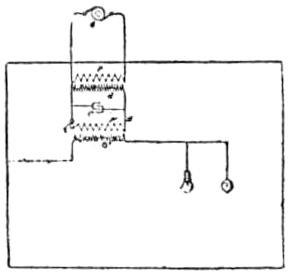
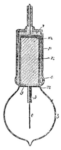
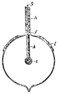
In the accompanying engravings, which illustrate Mr. Tesla's apparatus, Fig. 1 is a diagram of a system, and Figs. 2 and 3 are vertical sectional views of special forms of light-giving devices.
G is the primary source of current or electrical energy, in the present illustration an alternating current generator of comparatively low electromotive force. The potential of the current is raised by means of an induction coil, having a primary, P and a secondary, S. This secondary charges a condenser, C, and this condenser discharges through or into a circuit, A, having an air-gap, a, for maintaining a disruptive discharge. By the means above described a current of enormous frequency is produced. To convert this into a working current of very high potential, in the circuit A is connected the primary P' of an induction coil having a long fine wire secondary S'. The current in the primary P' develops in the secondary S' a current or electrical effect of corresponding frequency, but of enormous difference of potential, and the secondary S' thus becomes the source of the energy to be applied to the purpose of producing light.
The light-giving devices may be connected to either terminal of the secondary S'. If desired, one terminal may be connected to a conducting wall of a room or space to be lighted, and the other arranged for connection of the lamps therewith. In such case the walls should be coated with some metallic or conducting substance in order that they may have sufficient conductivity. The lamps or light-giving devices may be ordinary incandescent lamp; specially designed lamps are now preferred, however. This lamp consists of a rarefied or exhausted bulb or globe which incloses a refractory conducting body, as carbon, of comparatively small bulk and any desired shape. This body is to be connected to the secondary by one or more conductors sealed in the glass, as in ordinary lamps, or is arranged to be inductively connected thereto. For this last named purpose the body is in electrical contact with a metallic sheet in the interior of the neck of the globe, and on the outside of said neck is a second sheet which is to be connected with the source of current. These two sheets form the armatures of a condenser, and by them the currents or potentials are developed in the light-giving body. As many lamps of this or other kinds may be connected to the terminal of S', as the energy supplied is capable of maintaining at incandescence.
In Fig. 3, b is a rarefied or exhausted glass globe in which is a body of carbon e. To this is connected a metallic conductor, f, which passes through and is sealed in the glass wall of the globe, outside of which it is united to a copper or other wire, g, by means of which it is to be electrically connected to one pole or terminal of the source of current. Outside of the globe the conducting wires are protected by a coating of insulation, h, of any suitable kind, and inside the globe the supporting wire is inclosed in and insulated by a tube or coating, k, of a refractory insulating substance, such as pipeclay or the like. A reflecting plate, l, is shown applied to the outside of the globe b. This form of lamp is a type of those designed for direct electrical connection with one terminal of the source of current; but there need not be a direct connection, for the carbon or other illuminating body may be rendered luminous by inductive action of the current thereon, and this may be brought about in several ways. The preferred form of lamp for this purpose is shown in Fig. 2. In this figure the globe b is formed with a cylindrical neck, within which is a tube or sheet, m, of conducting material on the side and over the end of a cylinder or plug, n, of any suitable insulating material. The lower edges of this tube are in electrical contact with a metallic plate, o, secured to the cylinder n, all the exposed surfaces of such plate and of the other conductors being carefully coated and protected by insulation. The light-giving body e, in this case a straight stem of carbon, is electrically connected with the said plate by a wire or conductor similar to the wire f, Fig. 3, which is coated in like manner with a refractory insulating material, k. The neck of the globe fits into a socket composed of an insulating tube or cylinder, p, with a more or less complete metallic lining, s, electrically connected by a metallic head or plate, r, with a conductor, g, that is to be attached to one pole of the source of current. The metallic lining s and the sheet m thus compose the plates or armatures of a condenser.


