Nikola Tesla Articles
Tesla's System of Electric Lighting with Currents of High Frequency
In his lecture delivered before the American Institute of Electrical Engineers,1 Mr. Nikola Tesla dwelt at length upon the fact that the direct application of electro-magnetic waves to the production of luminous effects was impracticable and that for this purpose electro-static waves or thrusts must be employed. To make these effects available in practice, however, it is necessary to employ currents of very high frequency and of very high potential.
In a patent just issued to Mr. Tesla on this method of electric illumination, he draws attention to the mechanical difficulty of obtaining the necessary high frequency of alternations, and hence he avails himself of the principle of the disruptive discharge. The current of high frequency is produced by the disruptive discharge of the accumulated energy of a condenser maintained by continuously charging the condenser and discharging it disruptively, in connection with an induction coil which generates the high potentials required.
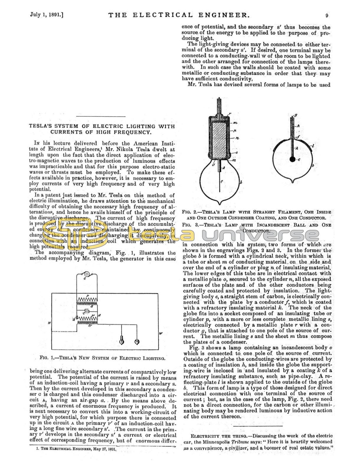
The accompanying diagram, Fig. 1, illustrates the method employed by Mr. Tesla, the generator in this case being one delivering alternate currents of comparatively low potential. The potential of the current is raised by means of an induction-coil having a primary P and a secondary S. Then by the current developed in this secondary a condenser C is charged and this condenser discharged into a circuit A, having an air-gap a. By the means above described, a current of enormous frequency is produced. It is next necessary to convert this into a working-circuit of very high potential, for which purpose there is connected up in the circuit A the primary P' of an induction-coil having a long fine wire secondary S'. .The current in the primary P' develops in the secondary S' a current or electrical effect of corresponding frequency, but of enormous difference of potential, and the secondary S' thus becomes the source of the energy to be applied to the purpose of producing light.
The light-giving devices may be connected to either terminal of the secondary S'. If desired, one terminal may be connected to a conducting-wall W of the room to be lighted and the other arranged for connection of the lamps therewith. In such case the walls should be coated with some metallic or conducting substance in order that they may have sufficient conductivity.
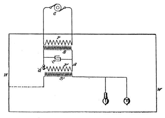
Mr. Tesla has devised several forms of lamps to be used in connection with his system, two forms of which are shown in the engravings Figs. 2 and 3. In the former the globe b is formed with a cylindrical neck, within which is a tube or sheet m of conducting material on the side and over the end of a cylinder or plug n of insulating material. The lower edges of this tube are in electrical contact with a metallic plate o, secured to the cylinder n, all the exposed surfaces of the plate and of the other conductors being carefully coated and protected by insulation. The light-giving body e, a straight stem of carbon, is electrically connected with the plate by a conductor f, which is coated with a refractory insulating material k. The neck of the globe fits into a socket composed of an insulating tube or cylinder p, with a more or less complete metallic lining s, electrically connected by a metallic plate r with a conductor g, that is attached to one pole of the source of current. The metallic lining s and the sheet m thus compose the plates of a condenser.
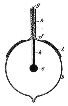
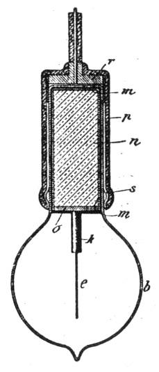
Fig. 3 shows a lamp containing an incandescent body e which is connected to one pole of the source of current. Outside of the globe the conducting-wires are protected by a coating of insulation h, and inside the globe the supporting-wire is inclosed in and insulated by a coating k of a refractory insulating substance, such as pipe-clay. A reflecting-plate l is shown applied to the outside of the globe b. This form of lamp is a type of those designed for direct electrical connection with one terminal of the source of current; but, as in the case of the lamp, Fig. 2, there need not be a direct connection, for the carbon or other illuminating body may be rendered luminous by inductive action of the current thereon.
1 The Electrical Engineer, May 27, 1891.