Nikola Tesla Books
Theoretical foundation of operation of Tesla's oscillator was provided in 1895 by Oberbeck.(29) Here we shall present some of the results of the author mentioned, which can help the reader to comprehend the phenomena in Tesla's oscillator.
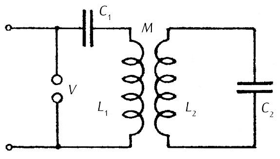
According to Oberbeck's theory the model of Tesla's oscillator was composed of two inductively coupled resonant circuits with a sparker in the primary circuit (figure 1 P). The primary circuit consisted of inductance of the primary L1 and capacitance C1. The secondary circuit was made by the secondary of transformer L2 and capacitance C1. Mutual inductance of coils was marked M and sparker v in the primary circuit. High voltage is charged to condenser C1 from a source of direct current or alternate current of low frequency.
Unlike the discharges from condenser in a simple oscillatory circuit analyzed by Lord Kelvin, discharge in the circuit of Tesla's oscillator was more complex due to the effect of the secondary oscillatory circuit. Had losses been neglected in oscillatory circuits, the current from the discharge would consist of two sin usoida I currents that were determined from the equation:
!$ {{{ω^{2}}_{a,b} = {{L_{1} C_{1} + L_{2} C_{2} \mp \sqrt{(L_{1} C_{1} - L_{2} C_{2})^{2} + 4 k^{2} L_{1} L_{2} C_{1} C_{2}}} \over 2 (1 - k^{2}) L_{1} L_{2} C_{1} C_{2}}}} !$
where I< stands for coefficient of coupling of transformer equal to !$ {M / \sqrt{L_{1} L_{2}}} !$. The above stated equation is obtained when differential equations are resolved for currents in the circuit presented in figure 1 Pin case of discharge from condenser C1 through a short connected sparker.
Frequencies ωa and ωb are not equal even if oscillations of the primary and secondary circuits were the same. Then there are L1C1 = L2C2 = 1/ωo2, giving:
!$ {{ω^{2}}_{a} = {1 \over ((1+k)L_{1}C_{1}}} !$ !$ {{{ω^{2}}_{b} = {1 \over ((1+k)L_{1}C_{1}}}} !$
For k = 0, ω_{a} and ω_{b} are the same and equal to ω_{o}. If k goes up, ω_{a} drops down and ω_{b} goes up. For k = 1 (the biggest possible coupling), {ω_{a}}^{2} = 0,5{ω_{o}}^{2}, and ω_{b} tends to become endless!
When L1C1 !$ {\neq} !$ L2C2, the flow of ωa and ωb with k is similar as in the quoted example, but no ωa and ωb are any longer the same for k = 0. In case of k = 1 only one solution is obtained:
!$ {ω^{2} = {1 \over L_{1}C_{1} + L_{2}C_{2}}} !$
To make Tesla's oscillator generate current of the same frequency, I< should be selected so as to equal either zero or one. For a successfully operating transformer in the domain of high frequencies, it is practically impossible to achieve k to be one, so another possibility should be chosen - to make k zero. However, in spite of a theoretical solution, this is obviously senseless, because the primary circuit remains alone thus no oscillations can be excited in the secondary. For small values of k and in cases of equal individual resonant frequencies of the primary and the secondary two currents in Tesla's transformers shall have mutually close frequencies. Approximate values of these frequencies are:
!$ {ω_{a} = {ω_{o}(1 - k/2)}} !$ !$ {ω_{b} = {ω_{o}(1 - k/2)}} !$
The preceding discussion was concerned with the case of osci11ation caused by charging condenser C1 with a shortcut at place v. In the real situation, energy of the condenser would be quickly spent and oscillations would end in a short while. That is why energy must be added externally and at the time intervals when the primary circuit breaks down at place v. Breakdown of the circuit occurs when the spark dies in the primary circuit. From the moment of breakdown of the primary circuit, the secondary circuit remains alone and oscillations therein continue, determined by the parameters of the secondary circuit. Frequency of oscillation was given as ωs2 = 1/L2C2, and in general differs from the frequency of the two components during the life of a spark in the primary circuit.
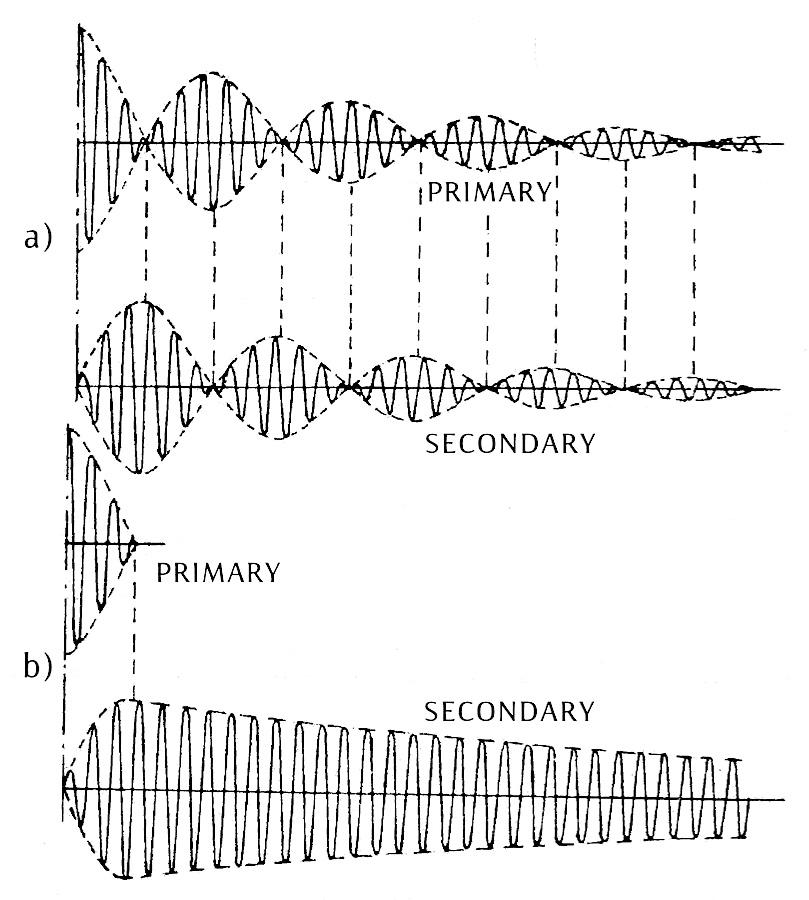
Depending on the duration of a spark in primary circuit, the form of the primary and secondary current shall change in Tesla's oscillator. The form of those currents is presented in figure 2P for a real oscillator, where subdued oscillations occur. In case of a long spark, multiple passage of energy from the circuit of the primary to the secondary shall occur and consequently the subdued oscillations are affected by losses in both circuits. Once spark terminated, the oscillations continue in the secondary circuit and are determined by the parameters of the secondary circuit. During sparking, the currents in the primary and secondary circuits consist of two components (similar as in the system without losses) with various factors of subductance.
The shape of currents presented in figure 2P.b is typical for the system of quick spark termination. Such a system of operation enables more efficient work of the oscillator, because there will be no passage of energy from one circuit into the other and no additional losses in the primary circuit either. Also, time interval in which the oscillator produces two oscillations is shorter and the one where the frequency of the oscillator is determined by the secondary circuit alone is longer.
According to Oberbeck's theory, the relation between the voltage in the condenser C1 before the start of discharge U1 and maximum voltage in the condenser C2 for the circuits without losses and with the same resonant frequency is equal to !$ {\sqrt{C_{2}/C_{1}}} !$. The momentary value of voltage in the condenser C2 is:
!$ {u_{2}(t) = {{U_[1} \over 2} \sqrt{C_{1}/C_{2}} (\cos ω_{a}t - \cos ω_{b}t)} !$
The momentary value of current through C2 is:
!$ {i_{2}(t) = {{U_{1} \over 2} \sqrt{C_{1} C_{2}} (\sin ω_{b}t - ω_{a} \sin ω_{a}t)}} !$
Amplitude of higher frequency current is bigger. Real circuits require considerably more complex analysis and several authors have been undertaking it. Drude's analysis(62) showed that in case of circuits with losses terms for u2(t) and i2(t) were changed so far as the ratio of transformation in the primary and the secondary was somewhat decreased and each component of voltage or current was multiplied with a term of form e-at (namely it exponentially decreases in time). Fleming and Dyke(31) measured the resonant curves of the Tesla oscillator operating at the ordinary and subdued sparks. They showed that with the ordinary sparker k it must be less than 0.1, namely k less than 0.3 in case of subdued spark to prevent oscillation on two (or even three) frequencies. Numerous values for k should change with the selected parameters of the circuit, but stronger coupling should always be available with subdued spark, causing no multi-frequency operation of the oscillator. The Tesla oscillator with the third oscillatory circuit, which Tesla called the additional coil was theoretically analyzed only years later.(46)


