Plans
Constructing a Tesla High Frequency Resonator
By Kenneth M. Swezey
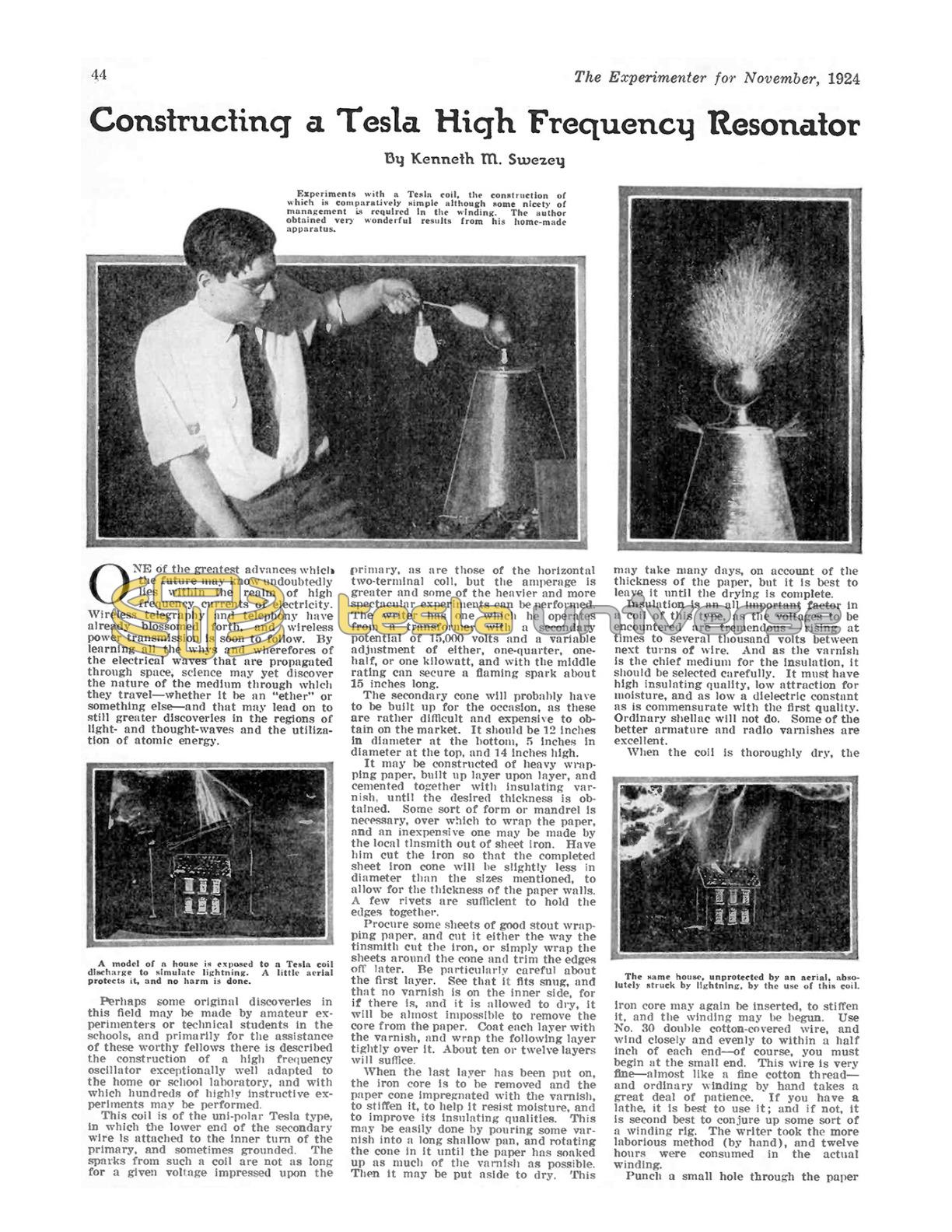
One of the greatest advances which the future may know undoubtedly lies within the realm of high frequency currents of electricity. Wireless telegraphy and telephony have already blossomed forth, and wireless power transmission is soon to follow. By learning all the whys and wherefores of the electrical waves that are propagated through space, science may yet discover the nature of the medium through which they travel — whether it be an "ether" or something else — and that may lead on to still greater discoveries in the regions of light- and thought-waves and the utilization of atomic energy.
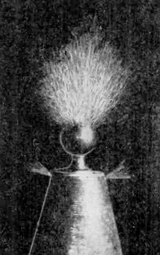
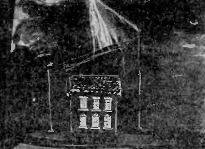
Perhaps some original discoveries in this field may be made by amateur experimenters or technical students in the schools, and primarily for the assistance of these worthy fellows there is described the construction of a high frequency oscillator exceptionally well adapted to the home or school laboratory, and with which hundreds of highly instructive experiments may be performed.
This coil is of the uni-polar Tesla type, in which the lower end of the secondary wire is attached to the inner turn of the primary, and sometimes grounded. The sparks from such a coil are not as long for a given voltage impressed upon the primary, as are those of the horizontal two-terminal coil, but the amperage is greater and some of the heavier and more spectacular experiments can be performed. The writer has one which he operates from a transformer with a secondary potential of 15,000 volts and a variable adjustment of either, one-quarter, one-half, or one kilowatt, and with the middle rating can secure a flaming spark about 15 inches long.
The secondary cone will probably have to be built up for the occasion, as these are rather difficult and expensive to obtain on the market. It should be 12 inches in diameter at the bottom, 5 inches in diameter at the top, and 14 inches high.
It may be constructed of heavy wrapping paper, built up layer upon layer, and cemented together with insulating varnish, until the desired thickness is obtained. Some sort of form or mandrel is necessary, over which to wrap the paper, and an inexpensive one may be made by the local tinsmith out of sheet iron. Have him cut the iron so that the completed sheet iron cone will be slightly less in diameter than the sizes mentioned, to allow for the thickness of the paper walls. A few rivets are sufficient to hold the edges together.
Procure some sheets of good stout wrapping paper, and cut it either the way the tinsmith cut the iron, or simply wrap the sheets around the cone and trim the edges off later. Be particularly careful about the first layer. See that it fits snug, and that no varnish is on the inner side, for if there is, and it is allowed to dry, it will be almost impossible to remove the core from the paper. Coat each layer with the varnish, and wrap the following layer tightly over it. About ten or twelve layers will suffice.

When the last layer has been put on, the iron core is to be removed and the paper cone impregnated with the varnish, to stiffen it, to help it resist moisture, and to improve its insulating qualities. This may be easily done by pouring some varnish into a long shallow pan, and rotating the cone in it until the paper has soaked up as much of the varnish as possible. Then it may be put aside to dry. This may take many days, on account of the thickness of the paper, but it is best to leave it until the drying is complete.
Insulation is an all important factor in a coil of this type, as the voltages to be encountered are tremendous — rising at times to several thousand volts between next turns of wire. And as the varnish is the chief medium for the insulation, it should be selected carefully. It must have high insulating quality, low attraction for moisture, and as low a dielectric constant as is commensurate with the first quality. Ordinary shellac will not do. Some of the better armature and radio varnishes are excellent.
When the coil is thoroughly dry, the iron core may again be inserted, to stiffen it, and the winding may be begun. Use No. 30 double cotton-covered wire, and wind closely and evenly to within a half inch of each end — of course, you must begin at the small end. This wire is very fine—almost like a fine cotton thread — and ordinary winding by hand takes a great deal of patience. If you have a lathe, it is best to use it; and if not, it is second best to conjure up some sort of a winding rig. The writer took the more laborious method (by hand), and twelve hours were consumed in the actual winding.
Punch a small hole through the paper cone with a needle, about a half inch from the edge, at the small end, and pass six inches of the wire through this to anchor it. Then put on a coating of varnish extending about an inch up the tube. When this becomes "tacky" carefully start the winding. After about five turns, give them a good coating of varnish and allow to dry thoroughly. This measure is important, as otherwise the turns would have a tendency to slide off the end.
Apply the varnish in little bits as you go along, and allow sections about an inch long to dry before proceeding, for the wire is so fine and the varnish so slippery when it is wet that one turn tries to climb up on top of the turn preceding it.
When the winding has been completed, it should be given four or five coats of the varnish; not too thin, either, for thin varnish tends to soften that which is already on.
Next come the wooden parts. The kind of wood does not matter so much as the fact that it should be well seasoned. All of the parts should be given at least three coats of the varnish.
The base should be an inch thick and 19 inches square, with a quarter-inch bevel around the edge to improve its appearance.
Two disks, each three-quarters of an inch thick, should be made to fit the ends of the cone, with shoulders cut as shown. If you have no lathe, the cheapest and best alternative is to have them made by a wood-turner. With homemade cones the dimensions may vary slightly, so it is well to measure very carefully before giving the woodworker your order.
From the center of the baseboard describe a circle 16 inches in diameter. On this, drill 16 three-eighth inch holes, at equidistant points, each about three-eighth inch deep. In these holes insert wood dowels 1 1/4 inches long, securing them with glue.
Then cut 4 two-inch lengths from a wooden rod 1 1/2 inches in diameter, also four lengths one inch long. The long ones are to serve as the feet for the base, and the short ones as the feet for the large disk which surmounts the base. Metal screws may be used on the base legs, if they are countersunk at least an inch. Dowels had better be used to secure the feet on the cone base.
The primary winding consists of five turns of one inch brass strip, wound about the circle of dowels, and the turns separated by strips of corrugated paper that have first been impregnated with the insulating varnish. Several turns of tape will bind the ends together.
Two large binding posts, connected under the base by two brass strips to the two ends of the primary complete the work on the base, except, perhaps, that a wire may be led from the inner turn to a binding post located near the center of the disk, so that the lower end of the secondary can be conveniently connected.
If the disks fit the cone tightly, no other support will be needed, and the whole apparatus can be set up or dismantled readily; but if they do not, or if a more rigid support is desired, one or two bakelite rods, threaded at the ends, and passing through the center of the cone, may serve to hold the ends together.
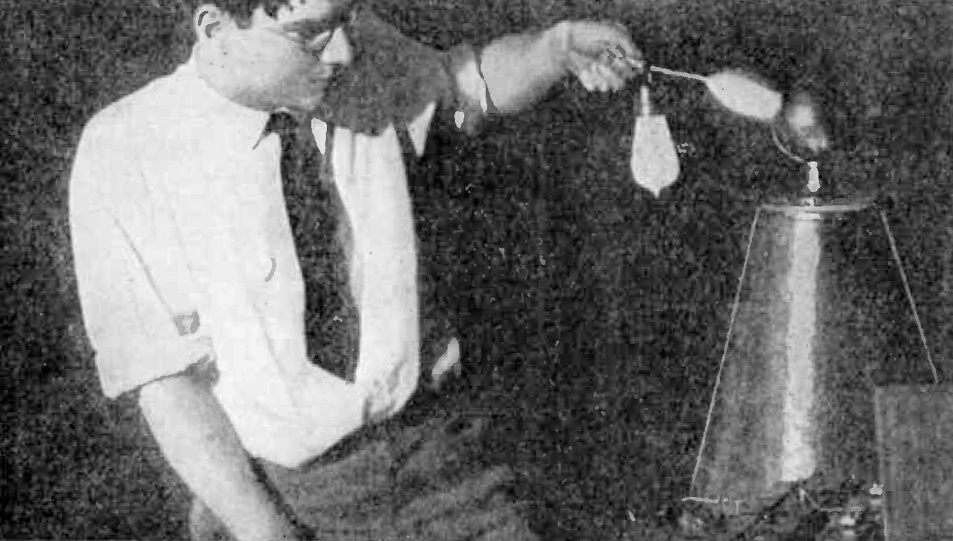
The ball on the top may be from 2 to 4 inches in diameter, and is of the type found on bedposts, brass railings, and andirons; the larger sizes are quite difficult to obtain by honest means. It is connected by a wire to the upper end of the secondary winding.
If the preceding instructions have been followed carefully, the resonator is now in workable shape, and you are ready to consider the auxiliary apparatus needed for its proper operation.
The transformer may range from one-quarter to one kilowatt, and may have a secondary rating of from 10,000 to 20,000 volts. The higher voltage will obviously produce a greater voltage in the resonator secondary. It is preferable that the transformer have some sort of magnetic leakage, to keep the gap from wastefully arcing under full load.
For best results, the condenser should have a capacity of about .01 mfd., and should be fully capable of withstanding the power you use. Mica condensers are ideal, for strength and compactness, and glass plate condensers come next. The author built one of photographic plates, the units being connected in series-multiple, which has withstood the strain well. Before that, while experimenting with different condensers, eight single units of the glass plate type were crashed within two minutes each.
The energy that can be put into the oscillator primary depends upon three things: the voltage of the transformer secondary, the capacity of the condenser, and the frequency of charge and discharge. These bear an intimate relationship, so none should be overlooked.
The spark gap is a very important factor. The chief essential is that it shall not allow the spark to arc, and that means that it must be kept cool. A rotary or a quenched gap is ideal. But an ordinary straight gap may be used providing a fan blows continuously upon it. With my apparatus the fan increased the high frequency spark length eleven inches! The gap must be opened as far as possible, without putting too much strain on the transformer secondary or the condenser.
It is essential that the resonator be tuned, for it is really nothing more or less than a type of oscillation transformer. And for this purpose a tuning inductance of about thirty turns of heavy wire or brass ribbon, is needed, with clips or a sliding contact to allow for variation. This number of turns is for a coil of eight inches average diameter. Only when tuned, will the resonator give effects from a violet haze to a crashing spark fifteen inches long.
The inner turn of the primary and the lower turn of the secondary, may be grounded or not as desired.